马上注册,结交更多好友,享用更多功能,让你轻松玩转社区。
您需要 登录 才可以下载或查看,没有账号?立即注册

×
本帖最后由 超级盾 于 2016-5-20 11:28 编辑
前面为纪念WREN发了一个《5bears制作Wren MW54涡喷发动机》的帖子,这里再转帖一下他制作ECU的纪录。
几点说明:
5bears制作ECU已经是十几年前的事了,转帖过来只是给大家一个参考而已;
帖子里不会有制作教程;
处于不同阶段的朋友看完会有不同的收获
原文是英文,这里也不做翻译了,如果确实读不懂又不愿意使用翻译工具,兴趣又不是那么高,就不用继续往下看了。
下面开始:
For the 5BECU, the tools of choice are the Microchip Flash series of controllers, specifically the 16F87X series. Thes cost approx. $8.00 U.S., are capable of low-voltage ICP (In Circuit Programming) for firmware updates, and have on-board Analog to Digital Conversion, Timers, and PWM output.
The code for the ECU is compiled with PicBasic Pro, a Basic language compiler available from MicroEngineering Labs. Assembly is using the Microchip assembler, available as a part of the MPLAB IDE, free from MicroChip. Programming of the Flash chips is done with the EPIC programmer, also available from MicroEngineering labs.

作者消息更新(最后更新是2002年)
ECU News 19 Feb 2002: Adventures inwireless turbine data transfer have been posted. 3 Feb 2002: Minor and modest revisions to the basic ECUcontinue. I am on version 150 as I write. Everything is runningwell. The PDF documentis still accurate except one additional user-defined value hasbeen added... the ability to adjust the accel ramp shape.Accelerating a gas turbine from a stable RPM is a complex processwhen done in a manner which precludes EGT spiking, especially atlow RPM. Early versions of the firmware would initially (andgently) accelerate the rotor from its stable RPM by incrementingthe 10-bit Pump PWM over a short period before allowing theacceleration profile to take over and really drive the turbine tothe commanded setting. This worked best for my MW-54. BillBlackburn's KJ-66, on the other hand, could skip this process, soI added coding which allows the user to define the shape of theinitial acceleration profile.

This drawing is pretty crude but perhaps it willbe helpful. The vertical axis is the amount of fuel added as timepasses to accelerate a turbine to a targeted setting. The overallheight of the curve is set with Pump Ramp Up insetup. Pump Ramp Up defines how long the acceleration profiletakes from a given RPM to a higher RPM. The new user setting iscalled Pump Ramp Up Profile, and determines howthe curve (until it reaches its peak value) is shaped. Note the left hand curve, which is suitable formy thrust MW54. Assuming the turbine is idling at a pump settingof 30 (using 8 bits in this example), and max RPM occurs at apump setting of 165, I snap the throttle from 0% to 100%. The ECUdetermines the pump delta, the difference between 30 and165, which is 135. It then examines the value of Pump Ramp Up. Ata Pump Ramp Up of 16, the profile is designed to accelerate fromidle to max in ~ 4 seconds. It then slices the pump delta intosegments, and begins to add these segments (over 4 seconds) tothe current pump setting until the desired pump target isobtained. For this example, let's assume that the software slices135 pump units into 15 segments, resulting in an increase of 9units of fuel per addition: 9 X 15 = 135. If I simply slam anadditional 9 units of fuel into the Wren at idle, the inertia ofthe rotor prohibits an instantaneous increase in the RPM, and theEGT spikes a bit. Not the best answer. So the ECU further slicesthe initial fuel delivery into a slope similar to the left curve.Once the rotor responds and the turbine accelerates, the profilebecomes benign and fuel can be aggressively delivered. Bill's KJ seemed to have no trouble snapping outof a low RPM regime. His turbine can tolerate a shape similar tothe one on the right. Fuel can be added much more aggressively,faster, than my Wren. Thus the ability to alter the shape of thecurve with Pump Ramp Up Profile. Entered duringSETUP (and accessible during RUN), the user can enter a value offrom 1 to 12, with a 1 value being a gentler shape such as theone on the left, and a 12 being similar to the right-hand curve. Why bother? If the turbine can handle the moreaggressive profile, throttle response is improved andacceleration times are reduced. It all leads to my lengthy questto create firmware which is adaptable to all model turbines. When will it be ready!?? I amclose! PLEEEEEEEEEEEZE be patient. As I mentioned on my homepage, I am a hobbyist with normal work and responsibilities, andI cannot devote 100% of my time to this project. Thanks fellows.
15 Nov 01: The ECU has run 3turbines so far,my MW54, Bill's KJ-66, and a borrowed RAM 500, all with greatsuccess. Bill initially experienced some hard starts andtorchings, which were caused by an exceptionally powerful fuelpump. This particular pump was running his turbine over a verynarrow output range, which means that even minute adjustments ofthe pump caused large changes in RPM. By choking the output ofthe pump slightly, and modifying the code somewhat, Bill's KJ wasup and running, and as of this date has had many, manyconsecutive runs with great success. Posted below are Bill'sprogrammed values, and the post-flight data showing how the ECUhandles the KJ-66. The data is either reported log data or timedobservations. | | Idle RPM | Max RPM | EGT Max | Accel Up Time | Decel Down Time | | Programmed Setting | 40K | 100K | 700 | Ramp Up = 12 | Ramp Dn = 6 | | Post-Flight | - | 100K | 685 | 4.0 - 4.5s | 3.0s |
We were both happyto see how well the ECU handles throttle bursts both up and down,keeping both RPM and EGT within limits. Accessories:While the LCD Data Display is very compact and can beflown with ease, we realize that many pilots would rather foregocarrying the weight, and a system is needed to allow users to seeturbine status at a glance. To satisfy this requirement, we aredesigning a direct, plug-in replacement for the LCD display whichwill consist of a set of LED's, one each green, amber, and red,which can be mounted in a model's canopy or any other convenientlocation. The LED's will be used for both start cues and turbinestatus. The pressure module is still in theconceptual stage and will take some time to develop, but will bea boon for those desiring a pressure-only system rather than atachometry system.
23 July 01: My neighbors are goingto lynch me with as much bench running as I have done inthe last couple of months. Everything seems to be falling inplace. There are some last-minute glitches, but nothinginsurmountable. I did discover that the ECU requires the use ofan ungrounded type k probe. Thermocouples come in 3flavors: grounded, ungrounded, and exposed junctions. Thejunction is where the two dissimilar metallic wires are welded toform the "tip" of the thermocouple, and this is wherethe voltage is generated proportional to heat. My ECU uses anAD595 chip to measure the EGT, and the 595 has a handy "openthermocouple" detector which can tell the ECU if the TC isburnt out or unplugged. This detector works great but only if theTC is of the ungrounded variety. Basically, this means that theTC wires inside the sheathe are electrically isolated from saidsheathing. If the wires contact the sheathe (a grounded probe)and the sheathe makes contact with the turbine exhaust cone, theEGT signal is grounded through the glow plug ground and the ECUreports an Open TC error. I have purchased a couple of ungroundedprobes and these work fine. I will offer some special ungroundedprobes in a 4" proble length which is perfect for the MW54on the online store. If you want to use your own type k probe,you must verify whether it is a grounded or ungrounded junction.To do this, you will need an ohmmeter. Measure the resistancebetween the probe's sheath and the pins of the TC's socket. Ifthe resistance is just a few ohms, the probe is a groundedjunction; if the resistance is several MOhms (millions of ohms)or greater, the probe is ungrounded and suitable for use. This issue is not critical as ungroundedprobes cost just a couple dollars more than the grounded variety.It is simply something which users must be aware of. Oh yes, I have discovered that the socketused for the LCD, a Molex C-Grid connector (kind of a locking R/Cstyle jack) is excellent in every way, but the force required toplug and unplug the LCD display is high enough to cause wear onthe cable. After the first half-dozen ECU's go out, the LCDconnector will be replaced with a 6-pin mini DIN plug identicalto a PS2 mouse connector, with the female plug being attached tothe ECU with a short run of cable, and the LCD display plug beingof greater length. This will allow the data terminal to beattached and reattached with ease and with less stress to the ECUboard. One other improvement is in the appearanceof the LCD display... the 4 phillips head screws seen in thepictures below were initially required to hold a cast plasticbracket which nests the pushbuttons and the LCD board. This wasre-engineered to eliminate these screws, allowing a much neaterappearance.
28 May 01: Updates, updates; muchof the work in the last month has been in sourcing parts, CADdrawings of the necessary case cutouts, and especially refinementof the RUN ramping of the fuel to the engine. It was easy to makean ECU which would safely drive the engine with slow throttleresponse, but to get really crisp performance required someimaginative and effective coding. I have reached a point in thiscoding where I am confident users will be pleased with throttleresponse.

|

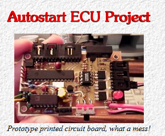
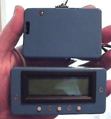
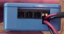
| I apologize for the quality of these photos... I just wanted to get some pictures up. To the far left is the ECU and companion LCD display, shown together in my hand for a relative size comparison. The slot cut into the ECU on the left edge is for my prototyping only - it allows me to sneak in a cable and reprogram the microprocessor.To the right are the outputs (and battery in) of the ECU. From left to right are propane solenoid output, fuel pump drive, and glow plug drive. These make use of locking connectors for security and reliability.
|


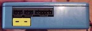
| The top photo shows the ECU inputs. From left to right: R/C input (optically isolated), tachometer, and the 6-pin connector for the LCD Display. The yellow jack is an industry standard miniature thermocouple plug.The bottom photo is a crude prototype of the LCD display, showing a rough idea of what the user will see when the engine is running. To make this photo, I attached my LCD display to my breadboarded ECU which does duty as a synthetic engine, which means that all the inputs are generated electronically, specifically the EGT and RPM signals. This lets me test all sorts of wild failure scenarios without risking my turbine!
Top Line: RPM (thousands), EGT, Pump output.
Bottom line: Run Mode/Fault annunciation, commanded throttle setting in %, and 3 dashes which show the status of gas solenoid, starter motor, and Glow, currently all OFF.
The final ECU will replace the Pump output with battery voltage on the display, but for testing purposes, the pump output is more important to me.
|
I have received 100 of the final printedcircuit board from Express PCB, and the quality is outstanding.These boards are fully solder masked and excellent in every way.Many small PCB refinements were made over the original PCB, andthe new board has been tested successfully to verify the tracesand functionality. Tachometry: there aremany different ways to successfully measure the engine's RPM. Thebest of these is, I believe, sensing via a Hall effecttransducer... see the online manual for details. But I realizetoo there are a lot of guys who simply want to use case pressure.To accomodate these enthusiasts, I am developing a separate pressuresensing module which will plug directly into the ECU TACH INport. This module will be quite compact and packaged like anelectric R/C speed controller with shrink-wrap tubing as a"case". During ECU setup, the user will specify whichtype of RPM sensing to use. In the case of the pressure sensor,the sensing module will have a barb which will of course beattached to the engine's compressor output. Inside the pressuresensing module, the pressure output is converted to a voltage,which is sampled by a dedicated microprocessor (the PIC 12C672).This uProcessor, in turn, will use either mathematicalmanipulation or a simple "look up" table to derive anappropriate RPM given the current case pressure. This RPM valueis sent to the ECU serially, and the user sees an "RPM"display indistinguishable from a true RPM transducer. Of coursethe accuracy is not as good as a true RPM sensor, and the enginewould best be derated 5000 or 10,000 RPM. Each pressure sensingmodule will need to be programmed for a specific RPM/Pressuremapping, so that there would be a "KJ-66 pressuresensor" and a "MW-54 pressure sensor", etc. All Ineed to program the module is a curve of RPM vs Case Pressure.This is normally provided by the engine designer, or can bederived by experimentation. For those patiently awaitingprice, delivery, etc, please bear with me. I want thisECU to be reliable, easy to use, safe, and affordable. Thanks!And I'll try to update more often too.
作者给出的参考链接
microEngineering Labs, Inc.
MCUmart.com Online Store
Microchip Technology Ince
BASIC Compilers for the PIC microcontroller
Basic Micro
PicBasic Pro,PicBasic,Basic Stamp,PIC Micro,and 8051 Microcontroller Projects
|
![]()