本帖最后由 超级盾 于 2016-5-10 20:28 编辑
Part 012: The Shaft
The shaft is a deceptively simple piece to make. It is easy to produce a beautiful, polished shaft that to the eye is flawless, but unless absolute concentricity is maintained, unless the diameters are perfect, imbalance, eccentricity, and bearing damage will eventually occur.
If you are making a shaft for the Wren 54 or any model gas turbine engine, take the time to read the text - it just may save you as much scrap as I generated!
5bears制作Wren MW54涡喷发动机
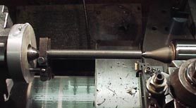
Turning of the shaft must take place between centers. Be sure your headstock center is running truly concentric by testing The relatively cylindrical portion just aft of the 60 taper with a sensitive dial indicator. Use a .0001" indicator if you have one, or at least a .0005" capable indicator. In my case, I ended up having to chuck a center in my 3-jaw, and then adjust the chuck to generate a perfect rotation. An aluminum collar engages the center barrel for dog rotation.
The material is 4140 steel. 4340 would be a better choice but since the material is used in the annealed state, and the mechanical properties of 4140 is very close to 4340, I elected to go with it.
For the tailstock, be sure it is perfect. Use a dial indicator, or take a very light cut along the entire length to check for perfect parallelism. If there is any taper (perhaps >.0004") correct it now. I had to shim my tailstock with .002" SS foil to achieve this, as it has no provision for set-over.
5bears制作Wren MW54涡喷发动机

Begin by roughing out the dimensions. The steel is quite tough and stringy. As the cut occurs, especially with any cut greater than perhaps .005", the shaft will spring away and result in a tapering cut. Measure frequently with a .0001" capable mike. Rough out with carbide or similar all surfaces (except the tapered portion) to perhaps .010" oversized.
5bears制作Wren MW54涡喷发动机
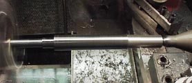
Grind a HSS bit to the correct form for 0 degrees lead, and give the tip a slight radius. I use a diamond hone to clean up the ground edges. This will be your "finishing" tool. Use this tool at the tailstock end only and get the critical surfaces for the bearing and the compressor shaft to perhaps +.001" If you are confident you can get a decent finish with accuracy, go for +.0005". But beware, with this steel, light cuts can produce a hit-or-miss action which may cut undersized. Better safe than sorry!
5bears制作Wren MW54涡喷发动机
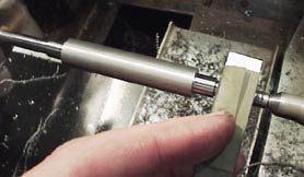
Next, take a piece of ground flat stock. Failing that, use a 3/8" blank lathe tool bit. Don't use a file! Wrap 400 grit wet/dry paper and evenly and carefully clean up the critical surfaces. Now mike the shaft portion being polished. If there is no taper, fine... if there is, a bit of "leaning" with the steel-backed paper can remove it. I have easily corrected tapers up to .001" with this technique.
When you are within .0004" of the desired diameter, switch to 600 grit. Knock it down another .0002". Now unleash some 1500 or 2000 grit paper. Check the fit as you go! My 688 bearings (these are regular bearings used as guages) had a perfect sliding fit at .3148". For your compressor or turbine, you must remove the shaft and check the fit, as no reamer made will consistantly cut to .2500". They tend to go oversized, especially in aluminum. I reamed my compressor to 1/4" as I wanted to screw-cut the threads fo accuracy and my lathe is 100% Imperial.
My compressor ended up with a tight but wringing fit at .2506". GO SLOW. Once the surfaces are undersized, that shaft is done. Trash it!
5bears制作Wren MW54涡喷发动机
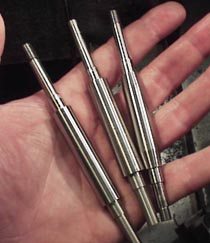
Here are THREE shafts, only one of which is acceptable. The shaft on the left had a turbine bearing surface cut too small due to a dull tool and material springiness. Into the scrap-box it went. As for the very promising middle shaft....
When you are ready to reverse the shaft and work on the turbine end, don't automatically assume that your precious compressor-end surfaces are concentric after the end-swap!
Much to my chagrin, I found after I had cut and polished the turbine end surfaces of the middle shaft that the compressor-end bearing surface was not running true... TIR was .001", absolutely unnacceptable. I know this shouldn't happen, but it did on my otherwise well-behaved Hardinge. So CHECK your runout and correct as necessary BEFORE working on the turbine end surfaces!
One other caveat: Use a high-quality live center. Realize that when you are roughing out, the work will heat and you may need to relieve expansion pressure on the tailstock. Before the critical cuts and polishing, let the shaft cool, and EVERY time you re-insert it, dial the tailstock barrel back to the same position for consistency. The light cuts and polishing don't heat up the work very much.
5bears制作Wren MW54涡喷发动机
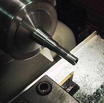
Once all of the bearing surfaces are perfect, cut the tapers with the top-slide... this procedure was not photoed. Use the same care when swapping the shaft end-for-end, and take the time to correct eccentricity even for the taper cuts. An eccentricity during the taper cut will induce an imbalance in the shaft.
The screw-cutting procedure was cake after the other surfaces were finished. I cut both ends with a left handed 1/4 x 28 thread, using a scrap of brass drilled and tapped with an appropriate tap as a guage. You want a fairly snug fit of the female to male threads.
5bears制作Wren MW54涡喷发动机
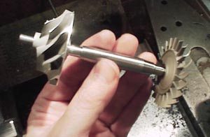
The shaft with compressor and turbine slipped on, after much sweating and angst. The critical surfaces are true to within .0001" of taper, and total runout of any surface relative to any other is maybe .00015 max. I say this not to toot my own whistle, but to show what can be done on a manual lathe with wet-dry paper and some care.
Cylindrical grinding machine? We don't need no stinkin' cylindrical grinding machine!
After I had posted the page seen above, I discovered still additional flaws in the shaft, which I described on my Home Page as dated updates. I have copied them here so others may learn from MORE of my mistakes.
23 Sep 2000: After struggling with the shaft turning, I had a lot of fun "spooling up" the compressor/turbine shaft assembly by squirting some shop air over the turbine blades. I did notice that installation and removal of the turbine, compressor, and standard 688 bearings scored the relatively soft steel of the shaft and actually loosened the fit of these parts very slightly. Having had much success with my nickel plating setup on other projects, I decided to see if I could actually build-up one of the scrapped shaft bearing surfaces with nickel and at the same time protect it both from corrosion and abrasion, the nickel surface being harder than the polished steel. I degreased and plated shaft #2 after carefully measuring the finished surfaces, and plated at .300 amp for the approx. 5.6 square inches of the shaft's surface area.
The result was enlightening... the shaft came out like a jewel. More importantly, the compressor portion of the shaft, which went in at .2503" came out with a dead-even .2514" plate, roughly .001" of nickel in one hour. This was heavier than I expected. I did some experiments... back in the lathe, I discovered the nickel was hard. An effort that would have removed .0005" of steel knocked down the nickel only .0001". I then took a propane torch and brought it up to a dull red heat, which would have produced a measure of scaling on bare steel. The result, a pretty blue/purple nickel, no signs of cracking or oxidation. This could have potential!
I am tempted to reduce my one good shaft to perhaps .0005" undersize, plate it for 45 minutes to get it back above the correct diameter, and then oh-so-carefully work these surfaces to perfection for the bearings, the compresor, and turbine wheel. The result should be a hard, durable, and perfect surface for the shaft components.
24 Sep 2000: I lied, I admit it. Grrr. A double-check of the surviving shaft among the trio already produced revealed worse runout than I had thought. I know that I initially measured around a tenth (.0001"), but a more careful check revealed runout over .001. I don't know how I missed it. The culprit resides in the action of flipping the shaft end-for-end during machining between centers. Another shaft is being turned, and this time I am simply going to chuck the stock and work the entire shaft in one setting. The right side of the shaft will be easy, but for the left I am going to have to gouge out a bit of stock below .2500" and attack it left to right with some left-handed turning tools. I know the dimensions of the critical areas, and I am going to polish them down to -.0005", and try the nickel plating procedure described below.
Stay tuned, this will either fail miserably as well or work like a champ!
1 Oct 2000: The nickle plating experiment was a success. I turned a new shaft with all surfaces at -.0008" or so, and after a very light polishing with 400 paper, I prepared the shaft for plating. I made absolutely sure that the shaft would rotate evenly in the solution so that the nickel would be deposited evenly as well.
I calculated that 1.3 hours in the tank would deposit a little over .001" of nickel, and should provide .0005" or so for final polishing of the bearing, turbine, and compressor surfaces. The shaft came out exactly as planned, perhaps a bit too much nickel but that is O.K. Back in the lathe, I worked the compressor end to perfection, but the turbine end gave me some problems. When I reached a dimension that produced a wringing fit, I found that the Inconel would seize and gall a bit, even though the bore of the turbine appeared very smooth. I was forced to take the shaft diameter down a bit farther so that the turbine wheel would install without excessive grab and gall. The bearing surfaces I have kept fat by about .0003" while I await delivery of the ceramic bearings. I do have some SS 688 bearings on hand, but at this point I am paranoid about using them as a guage, not knowing if the tolerances between these and the ceramic bearings are tight enough to warrant their use at this time. The ceramic bearings should arrive very soon! |
![]()