CHNJET喷气俱乐部

 找回密码
 立即注册

QQ登录

只需一步,快速开始

扫一扫,访问微社区

楼主: 超级盾

5bears制作Wren MW54涡喷发动机

[复制链接]
 楼主| 发表于 2016-5-10 19:32:00 | 显示全部楼层
欢迎大家在B站关注CHNJET
本帖最后由 超级盾 于 2016-5-10 20:30 编辑

The Combustion Chamber,part 2
Fuel injection sticks andcombustion chamber rear

  At the rear of the combustion chamber, held by a diameter of the NGV, are a set of 12 curved SS sticks which receive the fuel from the fuel pump via a set of hypodermic needles. The sticks, as well as the combustion chamber (cc) rear, come as part of the cc pack of parts, available from Wren and J.D. Enterprises. These would be difficult to make, and the pack of parts is highly recommended.
  The plans call for the sticks to be secured to the cc rear via spot welding, and the front of the sticks form a 54 mm circle towards the front of the chamber.


5bears制作Wren MW54涡喷发动机

5bears制作Wren MW54涡喷发动机

  The sticks as supplied from Wren are close but not exactly to print. Some of the sticks have more acute bends than others, which makes even positioning of the tips on the 54 mm circle difficult. I tried to bend them a bit more evenly, but once they are in this cut state, they are almost impossible to bend.
  Trimming to length is easy, though... I applied a bit of blue, layed them over the plans, and marked them with a scribe. A fine-toothed hack saw, followed up with a bit of sanding, took care of them.

5bears制作Wren MW54涡喷发动机

5bears制作Wren MW54涡喷发动机

  It is desireable to have as even a distribution of fuel at the front of the cc as possible. Rather than guessing, I created a thin aluminum jig, with 12 holes drilled on the desired 54 mm circle. A bit of reaming and fidgeting allowed me to assemble the sticks into the correct formation on the cc rear.

5bears制作Wren MW54涡喷发动机

5bears制作Wren MW54涡喷发动机

  Wren suggests using four spots per stick flange to secure the sticks into position. I was not able to get more than one per stick, and even then I blew 2 very small holes in the thin sheet steel. I elected then to seal and secure the flanges to the cc rear with silver braze. I selected Harris 45 Safety-Silv as the alloy of choice, as it fillets nicely and flows sluggishly at 1370 degrees f. This will provide a more secure joint than a thinner, more fluid braze.

5bears制作Wren MW54涡喷发动机

5bears制作Wren MW54涡喷发动机

  The joints are cleaned and wire brushed with a stainless brush, soap, and water. I used Harris flux for the brazing, and applied this material liberally... a piece the size of a lima bean smeared around each joint. Apply the flux to all 12 joints, and do the brazing in one sitting.
  The wire diameter I used was 1/32", and this worked perfectly. A very small propane torch is all that is necessary, as stainless steel does not conduct heat well and the local area heats quickly. Don't use oxy-acetylene, you would surely melt the steel, and it is simply not necessary.

5bears制作Wren MW54涡喷发动机

5bears制作Wren MW54涡喷发动机

  The silver braze flowed beautifully around the sticks, and produced a perfect fillet on the underside of the joint.
  With the jig removed, the sticks maintain their perfect and even spacing.
  On to the swirl jets!
回复 支持 反对

使用道具 举报

 楼主| 发表于 2016-5-10 19:34:50 | 显示全部楼层
本帖最后由 超级盾 于 2016-5-10 20:31 编辑

Compressor and TurbineNuts

  Why am I showing such a simple turning operation? Like many items in a turbojet, these parts are deceptively simple. What would work fine in a static situation would be absolutely unsuitable for a dynamic operation, where concentricity and imbalances are critical.
  The photos below show the compressor spinner nut. Similar care must be taken with the hex turbine nut of 316 SS. The main difference is the profiling of the nuts and the difficulty in centering the hex stock for the turbine nut.


5bears制作Wren MW54涡喷发动机

5bears制作Wren MW54涡喷发动机

  A section of round aluminum, in this case 6061, is chucked and the outer surface cleaned up in the lathe. Turn enough aluminum so that the turned portion can be parted and rechucked with sufficient stock extending for the nut. Measure the diameter of the parted, turned stock to within .0005 if you can.

5bears制作Wren MW54涡喷发动机

5bears制作Wren MW54涡喷发动机

  The stock is mounted in a mill, and the exact center is positioned for cross drilling of the tommy-bar hole. The end of the stock must be also located for longitudinal position of the hole. I used a small end mill to spot the round shaft for subsequent drilling. This helps minimize drill drift.
  I drilled mine .093 for the tommy-bar.

5bears制作Wren MW54涡喷发动机

5bears制作Wren MW54涡喷发动机

  Replace the stock in the lathe, and using a dial indicator, set it up for a dead-true turning operation. This will ensure the tommy-bar hole will remain centered.
  My nut will be threaded 1/4 - 28 LH. The nut is drilled perhaps .010" shy of the correct tap drill size, and a small boring bar is run in to center the hole. A final drilling is made for the tapping using a #3 drill. Using a tailstock attachment, the tap is started for at least 4 or 5 turns to ensure concentricity.

5bears制作Wren MW54涡喷发动机

5bears制作Wren MW54涡喷发动机

  The nut is removed and the threading finished in a vise. A bottoming tap is required.

5bears制作Wren MW54涡喷发动机

5bears制作Wren MW54涡喷发动机

  Maybe this isn't necessary, but again for absolute minimal eccentricity, I reassembled the shaft with the bearing, spacer, and compressor in place. Before tightening the tapped nut, I checked the runout of the shaft and corrected for 0 TIR. Do not skip this step!

5bears制作Wren MW54涡喷发动机

5bears制作Wren MW54涡喷发动机

  The profile isn't critical but should be smooth for the airflow. The outer diameter was turned down to match the compressor boss. Next, I used a homemade radius tool to generate a simple hemispherical shape at the nose. Form tools or freehand work will do fine, but be sure you don't use too much pressure and spring the shaft!
  Follow the turning with files and paper to smooth and polish the aliminum.

5bears制作Wren MW54涡喷发动机

5bears制作Wren MW54涡喷发动机

  The finished product, 0 TIR, shiny to boot!
回复 支持 反对

使用道具 举报

 楼主| 发表于 2016-5-10 19:36:41 | 显示全部楼层
本帖最后由 超级盾 于 2016-5-10 20:32 编辑

Part 006: The Case Front

  This was probably one of the more labor-intensive parts of the Wren turbine. While straightforward, it did require some interesting chucking solutions.
  The case front holds together most of the front end of the engine. The inlet cone of Delrin plastic is mounted in the middle of the piece, and the inner bolt-circle is drilled and tapped to accept this item. The larger bolt-hole circle contains 11 holes which attach the case front to the diffuser. Three of these are also service ports for fuel, gas, and lubrication. A fourth will probably become an air pressure tap. Additionally, the periphery is drilled and tapped to secure the outer case, along with an o-ring groove for a section of viton cord.
  At the back of the case front, the profile is rounded to accept compressor output and direct it to the combustion chamber area.


5bears制作Wren MW54涡喷发动机

 5bears制作Wren MW54涡喷发动机

  A short stub of 6061 aluminum was chucked and faced both sides. The outer diameter was also turned to size, and the stock bored to 1/2" deep to accept the Delrin nozzle.
  I elected to turn the rear portion first, which is nothing more than a 6mm radius fillet. The rear of the piece is first roughed out with a standard boring tool.

5bears制作Wren MW54涡喷发动机

 5bears制作Wren MW54涡喷发动机

  Next, a form tool is mounted, and the interior smoothed and a 6mm radius fillet is cut into the periphery. Note the WIDE (but thin) swarf generated by the form tool. The form tool should be ground somewhat less than 6mm radius, as only a portion of the cutting edge can be used at once, the overall shape being generated by slight jogs of the carriage and cross-slide levers.
  The interior is deburred and polished. Not shown is the cutting of the o-ring groove on the exterior diameter using a fine parting tool.

5bears制作Wren MW54涡喷发动机

 5bears制作Wren MW54涡喷发动机

  The entire stub is mounted in the mill. Again, X,Y coordinates were generated, and the 2 bolt-circles drilled, a total of 17 holes. I drilled through the case front and into the stock enough so that after parting off, I could reverse the case front and remount it on the same stub for machining of the front of the part.
  This need only be done for the inner circle which will hold the intake cone. The case front was parted off with enough stock for cleanup to final width, and the stub, with previously spotted holes, was drilled through for 3-48, the size I will use to secure the inlet cone.

5bears制作Wren MW54涡喷发动机

 5bears制作Wren MW54涡喷发动机

  My camera failed me, so I was unable to record a few of the steps. The inner circle was tapped 3-48, and the case front was reversed and mounted back onto the stub using 3 3-48 SHCS run in from the back of the stub. This allowed me to fully machine the front of the part after centering on the lathe.
  Machining required here was nothing more than a few lightening steps cut into the aluminum.
  Pictured here is the rear of the case front which mates with the diffuser. The o-ring groove can be seen on the perimeter, and the 6mm fillet is apparent as well. The black delrin cone was inserted into its proper place in the bore.

5bears制作Wren MW54涡喷发动机

 5bears制作Wren MW54涡喷发动机

  A frontal view. The case front, with inlet cone attached, is resting on the diffuser with the compressor wheel in place.
  This part concludes the major work on the turbine. All that remains now is plumbing and a test stand!
回复 支持 反对

使用道具 举报

 楼主| 发表于 2016-5-10 19:53:57 | 显示全部楼层
本帖最后由 超级盾 于 2016-5-10 20:34 编辑

Service ports, adaptors,and lube line

  After a week or so asking for Festo sources, I gave up and turned some adapters from mild steel for 10-32 push-to-connect tube fittings. These required some modifications to the front of the engine, and while a tad large aesthetically, they will allow me to easily select from a vast selection of fittings.


5bears制作Wren MW54涡喷发动机

5bears制作Wren MW54涡喷发动机

  Shown here are 4 steel adapters, 4 stainless service connectors, and a Legris 4mm tube fitting secured to a fifth adapter. The service connectors were easy to turn, but the drilling was tedious due to the toughness of the steel. Each required drilling through .059" for almost 1/2". I did break one drill before it was complete.
  In use, the pipes are silver brazed to the fat ends, and the service connector pushed through the diffuser from the rear. Over this goes the case front, and then one of my turned adapters is srewed down to secure.

5bears制作Wren MW54涡喷发动机

5bears制作Wren MW54涡喷发动机

  To prevent corrosion, the steel adapters were nickle plated. Here are all 5 adapters on a wire ring, suspended in the nickle solution. The anode can be seen inside a cloth bandage to the rear of the bucket. 2.0 volts created a 500 mA plating action for 30 minutes.

5bears制作Wren MW54涡喷发动机

5bears制作Wren MW54涡喷发动机

  In place on the case front. The case front and the cone had to be spot-faced to accept the 5/16" wide base of the adapters. The adapter at 4:00 has a Legris fitting attached.

5bears制作Wren MW54涡喷发动机

5bears制作Wren MW54涡喷发动机

  A view at the rear of the diffuser, showing the lube line. The air filter cover is secured with 3-48 SHCS. Also seen are the spot-faced service port locations around the periphery of the diffuser. A simple steel clip helps secure the lube line, which can be seen entering the front bearing recess at 8:00.
回复 支持 反对

使用道具 举报

 楼主| 发表于 2016-5-10 19:55:35 | 显示全部楼层
本帖最后由 超级盾 于 2016-5-10 20:34 编辑

Balancing the shaft

  Not having access to a dynamic balancer, I used the tried and true method described by Wren in the instruction manual. Both the compressor (not shown) and the turbine wheel were balanced in this fashion.


5bears制作Wren MW54涡喷发动机

5bears制作Wren MW54涡喷发动机

  A simple aluminum tube was turned for this exercise. Be sure the bearing outer diameter in the tube is relatively loose... you don't want the races to pop apart upon disassembly.
  The bearings and appropriate spacer are mounted on the shaft, along with either the turbine or compressor wheel and nut. I found that by popping loose the seal from a set of cheap 688 BB and washing out the grease with mineral spirits, that I had a shaft which free-wheeled better than the ceramic bearings. This has the added benefit of keeping the ceramic bearings free of any contamination prior to use.

5bears制作Wren MW54涡喷发动机

5bears制作Wren MW54涡喷发动机

  The shaft must be absolutely free-wheeling, with almost zero drag, for this to work properly. I occasionally added drops of mineral spirits to help things along. I also found that spinning up the shaft to perhaps 5,000 RPM with some shop air, and holding it there for a minute or so, helped the bearings seat a bit and allowed even less drag.
  The tube is placed on a surface plate and with fingertip pressure gently rocked back and forth through perhaps 10mm of distance. The heavy portion will work its way to the bottom. This is marked with a felt pen, and repeated to be sure it is an actual heavy spot.

5bears制作Wren MW54涡喷发动机

5bears制作Wren MW54涡喷发动机

  The turbine wheel has a balance ring cast into the root of the wheel. This is slowly ground away, and the process repeated until no discernable imbalance remains. Be sure to polish the area up a bit when you get close to minimize any chance of a stress crack or fracture developing.
  For the compressor wheel, the back face is gently filed or sanded, again being careful not to create any weak spots!
回复 支持 反对

使用道具 举报

 楼主| 发表于 2016-5-10 19:57:18 | 显示全部楼层
本帖最后由 超级盾 于 2016-5-10 20:35 编辑

The fuel ring

  The fuel ring mounts to the aft of the combustion chamber, encircling the flange which grips the NGV. This helps pre-heat the fuel. A single brass line delivers kerosene to the ring from one of the service ports.


5bears制作Wren MW54涡喷发动机

5bears制作Wren MW54涡喷发动机

  For all of the internal plumbing, I chose to use drawn copper tube rather than brass, as copper bends and handles far easier.
  (Note: Mike Murphy from Wren Turbines has since informed me that copper is not a good choice, as it may work harden from subtle vibrations and eventually split, releasing fuel and potentially causing an immediate and catastrophic overspeed! Be warned!)
  The rear of the combustion chamber was used as a guide to bend and cut the fuel ring shown. The "T" and the fuel delivery pipe was also a simple bend job. Distance front to rear is important.

5bears制作Wren MW54涡喷发动机

5bears制作Wren MW54涡喷发动机

  The ring is brazed to the delivery pipe, which in turn is braced to a service connector. Like so much else in this project, I tossed it in the nickle tank prior to drilling the holes for the twelve 316SS needle fuel injectors. The nickle is very resistant to corrosion, and will help preserve the piping in this extreme environment.
  The 12 holes were drilled #76, and the needles cut and inserted. Great care was taken to keep the needles clear of dust and debris. They were inserted roughly 1/2 way through the diameter of the ring tubing.
  Brazing the ring was tricky. The copper absorbs heat, and it is easy to exhaust the flux at the joint to be brazed. Use plenty of flux, and direct the flame so that as little as possible impinges directly on the needles. Try to do all 12 in one sitting.

5bears制作Wren MW54涡喷发动机

5bears制作Wren MW54涡喷发动机

  After cleanup, the ring was connected to a propane source and the needles tested. All passed with flying colors!

回复 支持 反对

使用道具 举报

 楼主| 发表于 2016-5-10 19:59:17 | 显示全部楼层
本帖最后由 超级盾 于 2016-5-10 20:36 编辑

Final Assembly and FirstRun!

  Having had much of the month of October free, I was able to make good progress in putting the engine together. The results are shown below.
  As for the running, please bear in mind I have never run a model turbine before!


5bears制作Wren MW54涡喷发动机

5bears制作Wren MW54涡喷发动机

  I did not photograph any of the operations dealing with the outer case. Somewhere during construction, my engine "stretched" a bit and I couldn't use the Wren outer case wrap. I had already ordered some 0.4mm sheet stainless, so a bit of work with the shears produced an acceptable case... up to the point where I began to weld the seam. I apparently overheated the steel a bit and the case was hopelessly warped. Case #2 turned out nicely. One bit of warning: when you drill the holes to secure the case front and rear, it might be tempting to locate and drill the holes with the part in place to assure perfect alignment of the holes. The problem with this is that the burr produced in the case is both large and strong, and it will secure either the case front or rear inside very effectively, requiring a mallet to remove. I did some damage to my case rear in this way. So be sure to drill your holes in the case while the steel is still flat, or you can turn a piece of aluminum to a snug sliding fit to act as a sacrificial support member for the drilling operation.

5bears制作Wren MW54涡喷发动机
5bears制作Wren MW54涡喷发动机

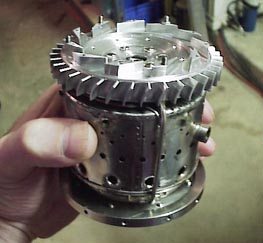
  I found that my diffuser would slide nicely from rear to front in the outer case, so I assembled the "guts" of the engine on my bench. In these two photos, one can see the cast NGV, case rear, combustion chamber, and diffuser properly assembled. On the top of the diffuser, you can also see the 4 service port screws which will later accept my 10-32 adapters for fuel, oil, gas, and air.
  With the assembly slid into the case, the case rear was secured. I used 12, 3-48 button head cap screws for better sealing. The front bearing was installed, as well as the shaft seal. Silicon grease helped this along.
  From the rear, I inserted the preload spring and tube into the shaft tunnel. The tube projected a bit under spring power, making insertion of the rotor tricky. I used finger pressure on the compressor spacer/oil seal on the inner race of the front bearing to keep the front bearing together! With care, there is no danger of the balls popping free.

5bears制作Wren MW54涡喷发动机
5bears制作Wren MW54涡喷发动机

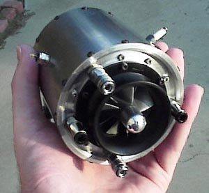
  Together at last! Note one glow plug and one spark plug. I was going to try a spark ignition to see if it is a viable means to ignite the engine. The three lower ports are the standard fuel, lube, and propane inlets. The fourth connector is for measuring case pressure. For now, there is no revs counter attached.

5bears制作Wren MW54涡喷发动机
5bears制作Wren MW54涡喷发动机

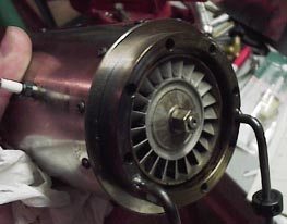
  I made use of the exact same ring I used to secure the cast NGV for turning to create a quick and dirty mount. Two additional holes were drilled, and a pair of 3/16" mild steel rods were inserted, TIG welded, and bent. Initial runs were made cone-off.

5bears制作Wren MW54涡喷发动机
5bears制作Wren MW54涡喷发动机

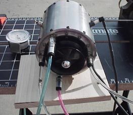
  On the stand at last! The board does nothing except support the nose of the engine. The two rods from the photo above were clamped in the workmate vise jaws. A second board c-clamped to the workmate held a liter of fuel, the fuel pump, speed controller, servo driver, and battery. The propane cannister was clamped to the legs of the stand.
  And the moment of truth had arrived! I was using a compressed air tank to spool the engine, and was surprised at the amount of air required to get it to spin up. After assembly, I had noticed that the rotor was a bit draggy, but assumed that it was the preload, and after verifying that the rotor was running free of interference from both the oil seal and the intake cone, I decided to give it a shot. Per the manual, I spun up the rotor, turned on the gas, and tried to get some ignition. Nothing from the spark, ditto the glo-plug. Grrr. Out came a small propane torch to get some ignition the manly way, via flames at the rear.
  Spun up again, I removed the air, let it spin down, and touched off the gas. Whooomp! Wow! Add more air and gas! I watched in horror as the revs decayed and the EGT began to skyrocket through 650! I groped for the gas valve and shut it down, all in seeming slow motion. I had visions of molten parts spewing out the rear through a fractured turbine wheel. Something was seriously amiss.
  After a few seconds, I felt better, as I realized I had left my EGT meter in fahrenheit! Ooops! Heh heh. But the rotor was still too stiff, and regardless of the EGT, the engine wasn't accelerating.
  Back on the bench, I removed the rotor assembly, and discovered the preload spring had been fouling the shaft. Mike Murphy, the Wren genius, had WARNED me of this possibility in an email yesterday, and sure enough it had happened to me. The shaft was lightly scored but still entirely useable. I installed a second preload spring made to better tolerances, and was entirely gratified to feel a nice, smooth spin with much less drag than before.

5bears制作Wren MW54涡喷发动机
5bears制作Wren MW54涡喷发动机

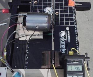
  Mounted again, I repeated the entire process. Spin up, add gas, ignite, replace air, and watch as the EGT gently rises and the engine accelerates! Mike had also warned me to add the fuel slowly. This I did, and the fuel touched off with a nice Whump and my little Wren began to sing!
  Not having a rev counter, I limited my case pressure to 14 psi or about .95 bar, which produced the photo as shown... EGT 495 celsius. The sound was sweet, and the engine behaved perfectly.
  I'm sorry I didn't take any thrust measurements, but stay tuned, I will get these ASAP.
  Thank you Wren for this fine little engine!
回复 支持 反对

使用道具 举报

 楼主| 发表于 2016-5-10 20:00:52 | 显示全部楼层
本帖最后由 超级盾 于 2016-5-10 20:37 编辑

Test run 17 Nov 2000 Coneoff

  Reeking of kerosene (mmm kerosene!) even as I type... The last week or two has been spent working on (and calibrating) the test stand with the cannibalized fish scale transducer from Wal-Mart. In the end, it was a lot of work but I beleive it was worth it. It was not a simple matter of connecting a trolley to the transducer, because unless the engine pulls on the transducer in a purely axial fashion, the weight measurement will be low. I confirmed this by mounting a tube into the stand and via a pulley arangement, loaded the tube (simulating the engine, diameters were the same) with a known 5 lb weight. With the old linkage, the 5 lb weight produced a 3.5 lb reading.
  The linkage was redesigned so that when mounted on the exact engine centerline, the 5 lb weight produced a correct 5 lb measurement.


5bears制作Wren MW54涡喷发动机

5bears制作Wren MW54涡喷发动机

  The ground support box in its finished state. The box carries a 12v battery for all supporting items, and a 7.2v NiMH battery for the pump. Seen here are the case pressure guage, white master switch, red pump switch, the 10-turn "throttle", the LCD readout from the fish-scale, and a deluxe LED EGT readout.
  The really sad part is that after all the work, I took the box outside for the run and discovered the EGT meter is totally washed out by the sun! I didn't even think about that. I'll need to find an LCD-powered EGT meter to replace it.

5bears制作Wren MW54涡喷发动机

5bears制作Wren MW54涡喷发动机

  The final test stand. Note the spark plug, which works so well that I removed the glo-plug from the other port and plugged it with a SS cap.
  I am using some Legris quick-disconnect micro-couplers. These are extremely slick, and function exactly like full-sized shop air tool couplers. My understanding is that Legris sells a bunch of these to dentists for their drills.
  The quick disconnects are set up on the air tap (blue) and the gas tap (bottom). Lube is left, and fuel, right.

5bears制作Wren MW54涡喷发动机

5bears制作Wren MW54涡喷发动机

  A closeup of the thrust measurement linkage. Buried beneath the nose of the engine is the variable-length arm which pulls against the thrust transducer. The big ring in the middle is a simple clamp which can be adjusted up or down... this varies the leverage exerted on the transducer, and allows me to calibrate the stand.
  In the foreground is a lever operated cam which allows me to remove the engine's thrust from the transducer to allow resetting the scale to zero. A flick of the lever foreward releases the carriage for thrust measurements.

5bears制作Wren MW54涡喷发动机

5bears制作Wren MW54涡喷发动机

  Once again, the engine behaved perfectly, started easily, and had no bad tendencies at all! The recordings below were done on a cool (10C) day, unknown pressure.
  Also on this run, I checked the minimum case pressure I could idle at, and found it to easily idle at 1.5 PSI. Below that, the EGT began to creep up a bit.
  Earlier, I had a table of thrusts posted here on this page which was erroneous. To see accurate thrust measurements, click here for both cone on and cone off data.
回复 支持 反对

使用道具 举报

 楼主| 发表于 2016-5-10 20:03:12 | 显示全部楼层
本帖最后由 超级盾 于 2016-5-10 20:38 编辑

The Electric Starter andHousing, Part 1

  I remember well from my days as a T-37 student the thrill of cranking up the Continental J-69-T-25 engine for the first time. The J-69 was an ancient engine which bears a remarkeable similarity to our model turbojets... it was definitely equipped with a radial compressor. I'm not too sure of the turbine section, but I'd like to believe it was axial-flow. Any T-37 IP's want to correct me? The engine was equiped with an electric start motor, and with the exception of the lack of propane, startup was again like a model turbojet. The engine was motored, and at a certain percentage, the fuel flow was started, ignited, and the starter left engaged to another, higher percentage to keep the start cool. Sadly, due to the radial compressor, spoolup of the J-69 was agonizingly slow, and many a student and IP were killed by stall accidents in the pattern, with the engine unable to spool up in time to provide saving thrust.
  On THAT unhappy note, here is the serialization of the electric starter for the MW-54...


5bears制作Wren MW54涡喷发动机

5bears制作Wren MW54涡喷发动机

  The motor is a Speed 300. The Bendix-style actuator plans are from the GTBA members web site, courtesy of Mike Murphy. I modified the mechanism only very slightly to accomodate my Imperial tooling. Getting the spindle to extend and retract properly was tricky, and the internal spring must be "just right". Don't make the fits too tight!

5bears制作Wren MW54涡喷发动机

5bears制作Wren MW54涡喷发动机

  Rather than having the motor hanging out exposed, I wanted it concealed in a bullet nose like the commercial engine starters. The diameter chosen was 1.125", leaving a wall of .084". This was just adequate to allow a 32 TPI thread for the nose itself to seal the Speed-300 inside.
  The bar is turned to size, and the interior bored to accept a nice sliding fit of the motor and spindle assembly.

5bears制作Wren MW54涡喷发动机

5bears制作Wren MW54涡喷发动机

  The front of the housing is relieved and screw-cut 32 TPI.

5bears制作Wren MW54涡喷发动机

5bears制作Wren MW54涡喷发动机

  Another scrap of aluminum is bored for the hemispherical nose, leaving a shoulder in place in the interior to press on the motor case to secure, and relieved for the motor wires. The interior is also screwcut to fit to the housing.

5bears制作Wren MW54涡喷发动机

5bears制作Wren MW54涡喷发动机

  Threaded in place, I elected to apply a very fine coin knurl to the end cap. Using a simple computer program, I generated a series of diameters to cut so as to create a rough hemisphere with a parting tool. This is then smoothed with a file and wet-dry paper.

5bears制作Wren MW54涡喷发动机

5bears制作Wren MW54涡喷发动机

  Layed out, the case, with its 3 milled support slots, the end cap, and the motor/spindle assembly.

5bears制作Wren MW54涡喷发动机

5bears制作Wren MW54涡喷发动机

  All we need now are the support arms, see Part 2!
回复 支持 反对

使用道具 举报

 楼主| 发表于 2016-5-10 20:05:11 | 显示全部楼层
本帖最后由 超级盾 于 2016-5-10 20:38 编辑

The Electric Starter andHousing, Part 2

  In Part 1, I showed the sequences which generated a snug, bullet-nosed pod to contain the Speed-300 and clutch mechanism. Here, I will show one way to create elegant supporting arms which can be attached and detached in 45 seconds from the engine.


5bears制作Wren MW54涡喷发动机

5bears制作Wren MW54涡喷发动机

  With the pod complete, I needed to engineer the supporting arms. A tripod arrangement I decided would be best for rigidity (important) and appearance.
  To this end, I enlarged the Wren 54 side-view print to 2X scale, and verified the correct dimensions. Onto the center-line, I added a scaled, pencil drawing of the pod, which can be faintly seen next to the spinner nut. From there, it was a simple matter to generate a 2X scale outline of a pod arm, which needs to be produced as a set of 3.

5bears制作Wren MW54涡喷发动机

5bears制作Wren MW54涡喷发动机

  Scaling the drawing back down to 1X, I simply cut out the pattern and glued it to one of three aluminum blanks of 1/4" thickness. Rather than make 3 separate pieces, I decided to drill a series of 4 lightening holes which I then reamed to .1875". Using these holes, I inserted 2, 3/16" pins to hold them all together for milling. This ensures 3 identical pod arms and reduces the work required significantly.

5bears制作Wren MW54涡喷发动机

5bears制作Wren MW54涡喷发动机

  After milling and drilling, the sandwich of pod arms is shown here next to the pod itself.
  The leading edge of the arms is rounded to fit the milled slots which I cut in the pod. Attachment is 2 ea. 3-48 SHCS per arm into the body of the pod.

5bears制作Wren MW54涡喷发动机

5bears制作Wren MW54涡喷发动机

  Firmly attached, the pod/arm assembly is chucked and the ends of the arms which fit onto the outer case are bored to size, and with the cross-slide set at 34 degrees (the print-generated angle) the arm interiors are nicely profiled.

5bears制作Wren MW54涡喷发动机

5bears制作Wren MW54涡喷发动机

  Once attached, I reinserted the motor and tested the unit. It worked perfectly!

5bears制作Wren MW54涡喷发动机

5bears制作Wren MW54涡喷发动机

  All that remains is to route the wires through a slot planed into the interior of the body (no cheesy wires to disturb the bullet nose), down through one of the arms, and out at the junction of one of the lower arms and the case outer..

回复 支持 反对

使用道具 举报

您需要登录后才可以回帖 登录 | 立即注册

本版积分规则

sitemap|联系站长|版权说明|小黑屋|Archiver|手机版|CHNJET喷气俱乐部 ( 京ICP备15028347号-2 京公网安备 11011202000937号 )

GMT+8, 2024-11-21 22:30

Powered by Discuz! X3.4

© 2001-2023 Discuz! Team.

快速回复 返回顶部 返回列表