本帖最后由 超级盾 于 2016-5-10 20:41 编辑
A balanced compressor nutwith secure magnets
I finished and ran my engine before I gave any thought to tachometer sensing. This was a mistake - I should have incorporated the necessary mechanical modifications before final assembly, as once the engine is running well, it is not a good idea to tear it down.
As I progress in the ECU development, I realized that a reliable tachometer would be of huge benefit. The ECU could be programmed with just a pressure input, but self-starting would become a real challenge as there would be no way to properly verify rotation.
So a tachometer input is needed. The PIC series of microcontrollers have a very simple set of commands which will allow one to count the number of pulses arriving at a pin, either high or low pulses, and this lends itself to just about any reasonable sensor, either IR, Hall effect (magnetic) or inductive. I chose the hall sensor (Micronas HAL506UA), as they are very reliable, deliver a square pulse due to the built-in schmidt trigger, will not be affected by sunlight, and can operate up to 10 kHz, well beyond 160,000 RPM. The bad news with the hall sensors is the requirement for a magnet to actuate the chip. The first inclination is to mill a pair of pockets on the spinner nut and glue them in... this is bound to fail with the magnets departing the spinner at freakish velocities, potentially destroying the engine or harming bystanders. In the end, I mounted the magnets as shown.
5bears制作Wren MW54涡喷发动机
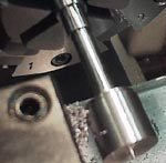
A piece of steel was chucked and turned to the compressor boss size plus perhaps .020" for cleanup. Aluminum would do as well but not be as durable, with the aluminum threads tending to loosen a bit over time with repeated installations. The slug was drilled and tapped 1/4" x 28 left hand.
A spare shaft was chucked and clocked to near 0 TIR, and the slug trued up a bit more, as the tapping operation will tend to cant the nut when finally in place on a shaft.
5bears制作Wren MW54涡喷发动机
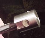
The magnet pockets were milled out using a 5C collet fixture. Any precision method of indexing the nut by two is acceptable. Just be sure to remove identical amounts of metal from both sides. Take the time to do it right!
The magnets are a pair of rare earth disks available at Radio Shack. They measure .197" dia by .060" thick, and are powerful little suckers. The magnets were superglued into place, with one magnet having its South pole to the outside, the other, its North pole. The South pole is the field which actuates the hall chip, so one revolution of the shaft = one pulse to the ECU. Two magnets are absolutely required for balance.
5bears制作Wren MW54涡喷发动机
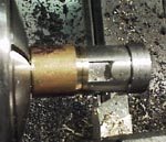
The spare shaft was again mounted in the lathe, and this time a brass spacer is used so that when the nut is tightened, it will bottom against the spacer and not the threads, with the spacer simulating the compressor boss. Simply bottoming the nut onto the threads of the shaft alone will not work... again, it will cant out of truth rather severely and not run true. Balance, balance, balance!
The nut is relieved left to right as shown for an aluminum sleeve to secure the magnets. I suggest a minimum wall thickness of the aluminum sleeve of .040", meaning the diameter of the nut will be reduced by .080". The magnets are also skim turned by this procedure, assuming the cylindrical shape of the rest of the nut.
The swarf from the magnets was amazingly powerful and caused clumps of steel chips to cling to the nut. Compressed air at high velocity works well to clean out the swarf.
5bears制作Wren MW54涡喷发动机
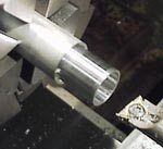
The aluminum sleeve is turned oversized outer diameter and precision bored for an interfernece fit to the relieved aft portion of the nut from the above step. A good rule of thumb would be sleeve bore = nut diameter - .0006". If you bore oversize, either try again, or use Loctite sleeve retainer in the next step.
5bears制作Wren MW54涡喷发动机
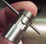
With the sleeve bored and parted, this is what you should see... the nut is already cross-drilled for a .093" tommy bar. The nut and sleeve are moved to a press or you can use a smooth-jawed machine vise....
5bears制作Wren MW54涡喷发动机
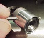
...and the sleeve is pressed into place. The magnets will NOT escape this assembly! Verify polarity of the magnets before you press the sleeve.
5bears制作Wren MW54涡喷发动机
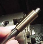
For absolute final truing and turning of the hemispherical nose, I turned another brass spacer, this one extending all the way onto the front bearing surface of the shaft.
5bears制作Wren MW54涡喷发动机

The shaft is mounted and an indicator applied to the surface of the shaft just aft of the nut. Adjust for 0 runout, using either a 4-jaw or an "adjust-tru" style of 3-jaw. DO NOT USE AN UNADJUSTABLE 3-JAW CHUCK! This would (unless you are very lucky) produce several thou runout and render the nut useless.
5bears制作Wren MW54涡喷发动机
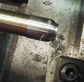
I used a simple PC program to generate the cross-slide settings for a hemispherical nose, shown here approx. 2/3 complete. Take light cuts, as the nut is held on only by its left-hand thread, and would spin right off the shaft under the forces induced in the lathe's normal rotation.
5bears制作Wren MW54涡喷发动机
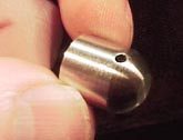
After roughing out, the nose is lightly filed with needle files and polished with wet-dry paper. The result is shown!
|
![]()