马上注册,结交更多好友,享用更多功能,让你轻松玩转社区。
您需要 登录 才可以下载或查看,没有账号?立即注册

×
本帖最后由 请叫我雷锋 于 2017-7-26 10:10 编辑
《Performance Evaluation and Design of Flight Vehicle Control Systems》
飞行器控制系统的性能评价与设计
作者:Eric T. Falangas
出版社:Wiley
出版时间:2016年
《Performance Evaluation and Design of Flight Vehicle Control Systems》

《Performance Evaluation and Design of Flight Vehicle Control Systems》

《Performance Evaluation and Design of Flight Vehicle Control Systems》《Performance Evaluation and ...

《Performance Evaluation and Design of Flight Vehicle Control Systems》

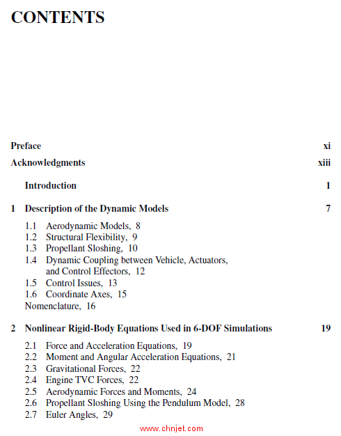
目录
Preface xi
Acknowledgments xiii
Introduction 1
1 Description of the Dynamic Models 7
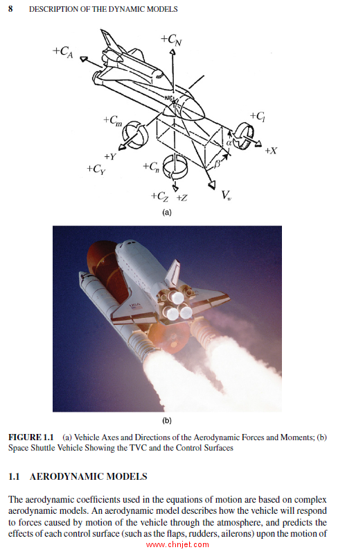
1.1 Aerodynamic Models, 8
1.2 Structural Flexibility, 9
1.3 Propellant Sloshing, 10
1.4 Dynamic Coupling between Vehicle, Actuators,
and Control Effectors, 12
1.5 Control Issues, 13
1.6 Coordinate Axes, 15
Nomenclature, 16
2 Nonlinear Rigid-Body Equations Used in 6-DOF Simulations 19
2.1 Force and Acceleration Equations, 19
2.2 Moment and Angular Acceleration Equations, 21
2.3 Gravitational Forces, 22
2.4 Engine TVC Forces, 22
2.5 Aerodynamic Forces and Moments, 24
2.6 Propellant Sloshing Using the Pendulum Model, 28
2.7 Euler Angles, 29
v
vi CONTENTS
2.8 Vehicle Altitude and Cross-Range Velocity Calculation, 30
2.9 Rates with Respect to the Stability Axes, 30
2.10 Turn Coordination, 31
2.11 Acceleration Sensed by an Accelerometer, 31
2.12 Vehicle Controlled with a System of Momentum Exchange Devices, 32
2.13 Spacecraft Controlled with Reaction Wheels Array, 33
2.14 Spacecraft Controlled with an Array of Single-Gimbal CMGs, 37
2.14.1 Math Model of a SGCMG Array, 38
2.14.2 Steering Logic for a Spacecraft with SGCMGs, 42
3 Linear Perturbation Equations Used in Control Analysis 47
3.1 Force and Acceleration Equations, 47
3.2 Linear Accelerations, 48
3.3 Moment and Angular Acceleration Equations, 50
3.4 Gravitational Forces, 51
3.5 Forces and Moments due to an Engine Pivoting and Throttling, 52
3.6 Aerodynamic Forces and Moments, 58
3.7 Modeling a Wind-Gust Disturbance, 70
3.8 Propellant Sloshing (Spring–Mass Analogy), 73
3.9 Structural Flexibility, 80
3.9.1 The Bending Equation, 85
3.10 Load Torques, 90
3.10.1 Load Torques at the Nozzle Gimbal, 91
3.10.2 Hinge Moments at the Control Surfaces, 93
3.11 Output Sensors, 97
3.11.1 Vehicle Attitude, Euler Angles, 97
3.11.2 Altitude and Cross-Range Velocity Variations, 98
3.11.3 Gyros or Rate Gyros, 98
3.11.4 Acceleration Sensed by an Accelerometer, 100
3.11.5 Angle of Attack and Sideslip Sensors, 101
3.12 Angle of Attack and Sideslip Estimators, 102
3.13 Linearized Equations of a Spacecraft with CMGs in LVLH Orbit, 104
3.14 Linearized Equations of an Orbiting Spacecraft with RWA and
Momentum Bias, 106
3.15 Linearized Equations of Spacecraft with SGCMG, 107
4 Actuators for Engine Nozzles and Aerosurfaces Control 109
4.1 Actuator Models, 111
4.1.1 Simple Actuator Model, 112
4.1.2 Electrohydraulic Actuator, 114
4.1.3 Electromechanical Actuator, 118
4.2 Combining a Flexible Vehicle Model with Actuators, 123
4.3 Electromechanical Actuator Example, 126
CONTENTS vii
5 Effector Combination Logic 137
5.1 Derivation of an Effector Combination Matrix, 138
5.1.1 Forces and Moments Generated by a Single Engine, 139
5.1.2 Moments and Forces Generated by a Single Engine
Gimbaling in Pitch and Yaw, 141
5.1.3 Moments and Forces of an Engine Gimbaling in a Single
Skewed Direction, 142
5.1.4 Moments and Forces Generated by a Throttling Engine or
an RCS Jet, 143
5.1.5 Moment and Force Variations Generated by a Control
Surface Deflection from Trim, 144
5.1.6 Vehicle Accelerations due to the Combined Effect from
all Actuators, 145
5.2 Mixing-Logic Example, 147
5.3 Space Shuttle Ascent Analysis Example, 152
5.3.1 Pitch Axis Analysis, 153
5.3.2 Lateral Axes Flight Control System, 163
5.3.3 Closed-Loop Simulation Analysis, 168
6 Trimming the Vehicle Effectors 171
6.1 Classical Aircraft Trimming, 171
6.2 Trimming along a Trajectory, 172
6.2.1 Aerodynamic Moments and Forces, 176
6.2.2 Moments and Forces from an Engine Gimbaling in Pitch
and Yaw, 178
6.2.3 Numerical Solution for Calculating the Effector Trim
Deflections and Throttles, 180
6.2.4 Adjusting the Trim Profile along the Trajectory, 183
7 Static Performance Analysis along a Flight Trajectory 187
7.1 Transforming the Aeromoment Coefficients, 188
7.2 Control Demands Partial Matrix (CT), 188
7.2.1 Vehicle Moments and Forces Generated from a
Double-Gimbaling Engine, 190
7.2.2 Vehicle Moments and Forces Generated by an Engine
Gimbaling in Single Direction, 191
7.2.3 Moment and Force Variations Generated by a Throttling
Engine, 191
7.2.4 Vehicle Moments and Forces Generated by Control Surfaces, 192
7.2.5 Total Vehicle Moments and Forces due to All Effectors
Combined, 192
7.3 Performance Parameters, 194
7.3.1 Aerodynamic Center, 194
7.3.2 Static Margin, 195
viii CONTENTS
7.3.3 Center of Pressure, 195
7.3.4 Pitch Static Stability/Time to Double Amplitude
Parameter (T2), 195
7.3.5 Derivation of Time to Double Amplitude, 196
7.3.6 Directional Stability (Cn
专业书籍
下载地址:(回复后可见)
|
![]()