马上注册,结交更多好友,享用更多功能,让你轻松玩转社区。
您需要 登录 才可以下载或查看,没有账号?立即注册

×
《Aircraft Loading and Structural Layout》
飞机载荷与结构布局
作者:
Denis Howe
PhD (Cranfield), SM (MIT), FRAeS, FlMechE
Professor Emeritus and formerly Head of the College of
Aeronautics, and Dean of Engineering,
Cranfield University, UK
出版社:Professional Engineering
出版时间:2004年
《Aircraft Loading and Structural Layout》

《Aircraft Loading and Structural Layout》

《Aircraft Loading and Structural Layout》

《Aircraft Loading and Structural Layout》

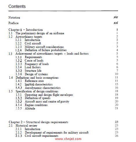
目录
Notation
Preface
Chapter 1 - Introduction
1.1 The preliminary design of an airframe
1.2 Airworthiness targets
1.2.1 Introduction
1.2.2 Civil aircraft
1.2.3 Military aircraft considerations
1.2.4 Definition of failure probabilities
1.3 Achievement of airworthiness targets - loads and factors
13.1 Requirements
1.3.2 Cause of loads
1.3.3 Frequency of loads
1.3.4 Load factors
1.3.5 Structure life
1.3.6 Design of systems
1.4 Definitions and basic assumptions
1.4.1 Reference axes
1.4.2 Inertial characteristics
1.4.3 Aerodynamic characteristics
1.5 Specification of design conditions
1.5.1 Operating and design flight envelopes
1.5.2 Definition of speeds
1.5.3 Aircraft mass and centre of gravity
1 S.4 Engine conditions
1.5.5 Altitude
Chapter 2 - Structural design requirements
2.1 Historical review
2.1.1 Introduction
2.1.2 Development of requirements for military aircraft
2.1.3 Civil aircraft requirements
rix
rxi
Contents
2.2 Current airworthiness codes
2.2.1 Introduction
2.2.2 Military aircraft
2.2.3 Civil aircraft requirements
2.3 Categories of aeroplanes
2.3.1 Military aircraft
2.3.2 Civil aircrali
2.4 Major categories of loading cases
2.4.1 Vehicle configuration and load cases
2.4.2 Symmetric flight cases
2.4.3 Asymmetric flight cases
2.4.4 Ground cases
2.4.5 Longitudinal load cases
2.4.6 Local loading and miscellaneous loading cases
2.5 Interpretation of loading cases
2.6 Design speeds
2.6.1 Introduction
2.6.2 Design speeds
Chapter 3 - Flight loading cases
3.1 Introduction
3.2 Symmetric flight manoeuvres
3.2.1 Introduction
3.2.2 Flight conditions in symmetric manoeuvres
3.2.3 The flight envelopc or n-Vdiagram
3.2.4 Pitching conditions
3.3 Asymmetric flight manoeuvres
3.3.1 Introduction
3.3.2 Rolling cases
3.3.3 Yawing/sideslip manoeuvres
3.4 Engine failure cases
3.5 Atmospheric turbulence and gusts
3.5.1 Introduction
3.5.2 Representation of gusts
3.5.3 Gust and turbulence requirements
3.5.4 Asymmetric gust requirements
Appendix A3 Roll performance requirements
A3.1 Milit~ry
A3.2 Civil
Chapter 4 - Rigid airframe dynamics
4.1 Introduction
4.2 Longitudinal trim conditions
4.2.1 Forces and moments in symmetric flight
4.2.2 Definition of aerodynamic terms
4.3 Static stability
4.3.1 Longitudinal static margin - controls fixed
4.3.2 Longitudinal manoeuvre margin - controls fixed
Contents
4.3.3 Lateral static stability
4.3.4 Directional static stability
4.4 General equations of motion
4.4.1 Introduction
4.4.2 Components of acceleration
4.4.3 Generalized force and moment equations
4.4.4 Initial steady trimmed conditions
4.4.5 Disturbed forces and moments
4.4.6 Rearrangement of the equations of motion and linearization
4.4.7 Nun-dimcnsionalization of the equations of motion
4.4.8 Decoupling of the equations of motion
4.5 Solution of the equations of motion
4.5.1 Introduction
4.5.2 Solution of the decoupled equations of motion using
the differential operator
4.6 Analysis of the longitudinal equations for loading actions calculations
4.6.1 Introduction
4.6.2 Definition of the non-dimensional longitudinal derivatives
4.6.3 Response of the aircraft to pitch control input
4.6.4 Response of the aircraft to changes in the thrust
4.7 Analysis of the lateral/directional equations
4.7.1 Introduction
4.7.2 Definition of lateral/directional non-dimensional derivatives
4.7.3 Decoupling of the lateral/directional equations of motion
4.7.4 Response of the aircraft to roll control input
4.7.5 Response of the aircraft to yaw control input
4.7.6 Response of the aircraft to changes in thrust
4.8 Comments on special configurations of aircraft
4.8.1 General
4.8.2 Aircraft employing fore-plane layouts
4.8.3 Tailless aircraft
4.8.4 All-moving horizontal stabilizer
Appendix A4 Characteristics of second-order linear
differential equations
A4.1 Introduction
A4.2 The Complementary Function
A4.3 The Particular Integral
Chapter 5 - Flight manoeuvre loads
5.1 Introduction
5.1.1 General comments
5.1.2 Trimmed flight
5.1.3 Manoeuvre loads
5.2 Modes of control motivator movement
5.2.1 Introduction
5.2.2 Unchecked mode
viii Contents
5.2.3 Checked mode
5.2.4 Excitation mode
5.3 Longitudinal cases - pitch motivator deflection
5.3.1 Steady flight conditions
5.32 Pitching acceleration
5.3.3 Analysis of the uncheckcd pitching manoeuvre
5.3.4 Analysis of the checked pitching manoeuvre
5.3.5 Comparison of the loads resulting from unchecked and
checked control movements
5.3.6 Summary of the loads on the horizontal stabilizer
5.3.7 Loads on trailing edge control devices
5.4 Lateral case - roll motivator deflection
5.5 Directional case - yaw motivator deflection
5.5.1 Introduction
5.5.2 Step input to thc yaw motivator
5.5.3 Sinusoidal input to the yaw motivator
5.5.4 Loads on the yaw control motivator
5.5.5 Lateral and yaw accelerations
5.6 Asymmetric horizontal stabilizer load due to sideslip
5.7 Application of flight manoeuvre load analysis
Chapter 6 - Loads due to atmospheric turbulence
6.1 The nature of atmospheric turbulence
6.1.1 General comments
6.1.2 Mathematical models of atmospheric turbulence
6.2 Analysis of the alleviated sharpedged gust - the
gust n-V diagram
6-21 The alleviating factor
6.2.2 Tbe gust n-V diagram
6.2.3 Horizontal stabilizer load due to a symmetric gust
6.2.4 Fore-plane layouts
6.2.5 Lateral gust load on the vertical stabilizer
6.3 The tuned gust approach
6.3.1 Symmetric gusts
6.3.2 Lateral gusts
6.4 Continuous turbulence analysis
6.4.1 Basis of continuous turbulence analysis
6.4.2 Application to aircraft gust response
6.4.3 Continuous turbulence gust gesign criteria
6.4.4 Determination of functions A and No
6.4.5 Stmctural response dynamic factors
6.5 Concluding remarks
Appendix A6 Example application of lateral two degree of freedom
continuous turbulence analysis
A6.1 Introduction
A6.2 Aircraft and case data
A6.3 Alleviated sharp-edged gust analysis
Contents
A6.4 Calculation of A and N,, for continuous turbulence analysis
A6.5 Application to design envelope analysis
A6.6 Application to mission analysis
Chapter 7 - Ground loads
7.1 lntroduction
7.1.1 General comments
7.1.2 Scope of the requirement codes
7.1.3 Aircraft design mass conditions
7.1.4 Aircraft attitude in the longitudinal plane
7.2 Summary of shock absorber design characteristics
7.2.1 Introduction
7.2.2 Shock absorber performance and efficiency
7.2.3 Pneumatic tyre characteristics
7.2.4 Shock absorber reaction factor and stroke
7.2.5 The energy absorption equation
7.2.6 Energy dissipation
7.3 Encrgy absorption requirements
7.3.1 Introduction
7.3.2 Landing vertical velocity requirements
7.3.3 Distribution of the vertical energy into the landing gear units
7.4 Load cases resulting from landing conditions
7.4.1 Inlroduction
7.4.2 Landing with drag and side load - Load Case (I)
7.4.3 Side load - Load Case (2)
7.4.4 High-drag landing - Load Case (3)
7.4.5 One-wheel landing condition - Load Case (4)
7.4.6 Rebound of unsprung parts - Load Case (5)
7.5 Load cases resulting from ground manoeuvring conditions
7.5.1 Introduction
7.5.2 Braking cases
7.5.3 Turning and pivoting
7.5.4 Take-off cases
7.5.5 Supplementary nose-wheel loads - steering
7.5.6 Towing loads
7.6 Operation from uneven surfaces
7.6.1 Introduction
7.6.2 Definitions of runway unevenness and the bump factor, F
7.6.3 Military aircraft steady brakmg cases
7.6.4 Take-off cases
7.7 Supplementary loading conditions
7.7.1 General
7.7.2 Directional control and nose-wheel castoring
7.7.3 Forward speed at and after touchdown
7.7.4 Taxiing and takeoff run
7.7.5 Unequal loads on wheels and tyres
7.7.6 Tyre clearances
Contents
7.7.7 Retraction and lowering
7.8 Absorption of horizontal energy - brake considerations
7.9 Effect of airframe flcxihility and other variahles
7.10 Example calculalion
Appendix A7 Dynamic analysis of landing
A7.1 Introduction
A7.2 The definition of the problem
A7.3 Derivation of landing gear spring and damping
characteristics
A7.4 Derivation of applied forces
A7.5 Kinetic energy terms
A7.6 Potential energy terms
A7.7 External work
A7.8 Derivation of the equations of motion
A7.9 Simplification and solution of the equations of motion
A7.10 Comments
Chapter 8 - Loading nn individual airframe components
8.1 Introduction
8.2 Additional overall considerations
8.2.1 Longitudinal acceleration and deceleration
8.2.2 Spinning
8.2.3 Ground handling loading
8.2.4 Crashworthiness
8.3 Lifting surfaces
8.3.1 Introduction
8.3.2 Bird strikes
8.3.3 Fuel systems - integral and hag tanks
8.3.4 Loading of control surfaces and high-lift devices along
the effective hinge-line
8.3.5 Control surface tail to wind case
8.3.6 High-lift devices
8.3.7 Wing-mounted spoilers and air-brakes
8.4 Fuselages
8.4.1 General comments
8.4.2 Deceleration cases
8.4.3 Pressurization
8.4.4 Bird strikes
8.4.5 Freight loading conditions
8.5 Powerplant installations - engine mounting loads
8.5.1 Introduction
8.5.2 United Kingdom military aircraft
8.5.3 Civil aircraft
8.5.4 Bird strikes - intakes
8.5.5 Location of powerplants
Contents
Appendix A8 Design formulae for transparency design under
bird strike conditions
A8.1 Introduction
A8.2 Penetration formulae
A8.3 Deflection analysis
Chapter 9 - Air-load distributions
9.1 Introduction
9.2 General comments concerning lifting surfaces
9.3 Span-wise loading of lifting surfaces in subsonic flow
9.3.1 Un-swept lifting surfaces
9.3.2 Span-wise loading of swept lifting surfaces
9.3.3 Span-wise loading distribution due to rolling
9.3.4 General comments on the span-wise loading of lifting
surfaces in subsonic flow
9.4 Chord-wise loading of lifting surfaces in subsonic flow
9.4.1 Components of loading
9.4.2 Location of the chord-wise centre of pressure and the
aerodynamic centre
9.4.3 Overall chord-wise load and moment
9.4.4 Chord-wise load distribution on basic aerofoils
9.5 Longitudinal air-load distribution on bodies in subsonic flow
9.6 Pressure distribution on lifting surfaces in supersonic flow
9.6.1 Pressure distribution on a lifting sdace of infinite aspect
ratio in inviscid supersonic Row
9.6.2 Pressure distribution on an unswept lifting surface of finite
aspect ratio in inviscid supersonic Row
9.6.3 Boundary layer effects
9.6.4 Swept wings with supersonic leading and trailing edges
9.6.5 Swept lifting surfaces with subsonic leading edges
9.6.6 Comments on the pressure distributions over lifting surfaces
in supersonic flow
9.6.7 Effect of yaw on the pressure distribution in supersonic flow
9.6.8 Pressure distribution due to control deflection in
supersonic flow
9.7 Air-load distribution on bodies and wing-body combinations in
supersonic flow
9.7.1 Isolated bodies
9.7.2 Air-load distribution on wing-body combinations in
supersonic flow
9.8 The contribution of overall loading at zero lift to the zero-lift
pitching moment
9.8.1 Introduction
9.8.2 Wing aerofoilsection camber
9.8.3 Lifting surface twist
9.8.4 Fuselage camber
xii Contents
9.8.5 Wing-body effect
9.8.6 Total zero-lift pitching moment
Chapter 10 - Specification and analysis of repeated loading
10.1 Introduction
10.2 Fatigue design requirements
10.2.1 Introduction
10.2.2 Civil transport aircraft
10.2.3 United Kingdom military aircraft
10.2.4 United Stales military aircraft
10.3 Assumptions made in the analysis of fatigue loading
10.4 Repeated load data
10.4.1 Presentation of data
10.4.2 Flight manoeuvre cases
10.4.3 Atmospheric turbulence
10.4.4 Landing gear loads
10.4.5 Other sources of significant repeated loading
10.5 Significance of repeated load cases
10.5.1 Introduction
10.5.2 Ground loading
10.5.3 Ground-air-ground load
10.5.4 Pressurization
10.5.5 Flight manoeuvre loads - symmetric
10.5.6 Flight manoeuvre loads - asymmetric
10.5.7 Conuol motivator loads
10.5.8 Flight gust loads
10.5.9 Landing loads
10.6 Specification of airframe life
10.7 The fatigue design process
10.7.1 Introduction
10.7.2 Initial phase of the design to combat fatigue
10.7.3 Selection of the design philosophy
10.7.4 Design process - safe life and fail-safe
10.7.5 Design process - damage tolerant
Chapter 11 - Aeroelastic considerations
11. I Introduction
11.2 Aeroelastic phenomena
11.2.1 Divergence
11.2.2 Reduction of control effect and reversal
11.2.3 Flutter
11.3 Structural response
11.4 Specified aeroelastic requirements
11.5 Stiffness criteria
11.6 Inertia and mass distribution
11.7 Structural damping
Contents
1 I .8 Miscellaneous stiffness and related considerations
11.8.1 Control surface backlash
11.8.2 Control surface and shroud distortion
11.8.3 Hinged doors, dive brakes, etc.
11.8.4 Overall wing aerofoil contour
Chapter 12 - Derivation of structural design data
12.1 Introduction
12.2 Basic aims of structural design
12.2.1 Introduction
122.2 Strength
12.2.3 Stiffness
12.2.4 Serviceability
12.2.5 Implication of advanced control systems
12.3 Analysis of requirements - structural design data
12.3.1 General procedure
12.3.2 Example of unrestrained beam analysis
12.3.3 Loading conditions in major design cases
12.4 Sources of load on primary structural components
12.4.1 Introduction
12.4.2 Overall loading on the wing
12.4.3 Fuselage loading
12.4.4 Landing gear
12.5 Reference and datum lines
12.5.1 Reference lines
12.5.2 Swept lifting surfaces
Appendix A12 Example of an unrestrained beam analysis
A12.1 Definition of the problem
A12.2 Overall load analysis
A12.3 Comments
Chapter 13 - Airframe materials and applications
13.1 Introduction
13.2 Airframe materials
13.2.1 General
13.2.2 Metallic materials
13.2.3 Fibre-reinforced composite materials
13.3 Criteria for the selection of materials
13.3.1 General
13.3.2 Static (ductile) strength
13.3.3 Fracture toughness
13.3.4 Stiffness
13.4 Application of aircraft matcrials
13.4.1 Metals
13.4.2 Composites~
13.4.3 Smart materials
13.4.4 Other airframe materials
xiv Contents
13.5 Material properties for initial structural design
13.5.1 Introduction
13.5.2 Stiffnesses
13.5.3 Allowable stresses - metals
13.5.4 Allowable stresses - fibre-reinforced plastic composites
Chapter 14 - Role and layout of structural members
14.1
Chapter 15 - Synthesis procedure - initial sizing of members
15.1 Introduction
15.1.1 Basic data
15.1.2 Distribution of loads
15.1.3 Synthesis technique
Introduction
Lifting surfaces - wings and stabilizers
14.2.1 Overall requirements
14.2.2 Span-wise beam concepts
14.2.3 Wing fuel tanks
14.2.4 Chord-wise location of spars
14.2.5 Rib location and direction
14.2.6 Fixed secondary structure
14.2.7 Hnrizontal stabilizer
14.2.8 Vertical stabilizers
Auxiliary surfaces
14.3.1 General
14.3.2 Hinged control surfaces
14.3.3 Pivoted control surfaces
14.3.4 High-lift systems
Fuselage
14.4.1 General considerations
14.4.2 Cross-section shape
14.4.3 Basic structural layout - outer shell
14.4.4 Frames
14.4.5 Doors, windows, and windscreen/canopies
14.4.6 moors
Attachment of lifting surfaces
14.5.1 Continuous cany-through structure
14.5.2 Wing loads passed round fuselage
Buried powerplants in combat aircraft
14.6.1 Introduction
14.6.2 Wing location
14.6.3 Engine removal
14.6.4 Special problem of vertical take-off and landing designs
Landing gear
14.7.1 Landing gear mechanical layout
14.7.2 Landing gear retraction
Contents
15.2 Box beam of lifting surfaces
15.2.1 Cross-section of the structural box
15.2.2 Torsional stiffness requirement
15.2.3 Overall torsion moment
15.2.4 Overall bending moment
15.2.5 Thickness of upper and lower box surfaces
15.2.6 Spar webs
15.2.7 Stringer configuration
15.3 Ribs
15.4 Auxiliary surfaces (controls. flaps, slats, and spoilers)
15-41 Hinaeisuuuort uositions
15.4.2 sizing ofihe miin elements
15.5 Fuselage
15.5.1 Pressurization
15.5.2 Torsion shear requirement
15.5.3 Overall bending
15.5.4 Determination of the skin thickness
15.6 Fuselage shell support frames
15.7 Main attachment frames and bulkheads
15.7.1 Heavily loaded frames
15.7.2 Pressure bulkheads
15.8 Floors
Chapter 16 - Important departures from elementary theory
16.1 Introduction
16.2 Buckling considerations
16.2.1 Introduction
16.2.2 Struts
16.2.3 Optimization of distributcd flange-stringer designs
16.2.4 Buckled shear webs
16.3 Cut-out: constraint, and sweep effects in box beams
16.3.1 Introduction
16.3.2 Bredt-Batho torsion - cut-outs and constraint effects
16.3.3 Constraint effects in swept-wing boxes
16.4 Joints
16.4.1 General
16.4.2 Transport joints
16.4.3 Production joints
16.4.4 Joint details
16.5 Cut-outs and load diffusion
16.5.1 Cut-outs
16.5.2 Load diffusion
Chapter 17 - Conclusions
17.1 Review and analysis
17.2 Loading calculations
Contents
17.3 Structural design
17.3.1 Introduction
17.3.2 Structural design check list
Appendix A17 Bibliography
Addendum AD1 - Example application of flight loading cases
ADI. 1 Scope of example
AD1.2 Cranfield A1 acrobatic aircraft
AD1.3 Aircraft data
AD1.3.1 General
AD1.3.2 Inertial characteristics
AD1.3.3 Geometry
AD1.3.4 Aerodynamic data
AD1.4 Definition of design loading conditions
AD1.4.l General - applicable requirements
AD1.4.2 Specification of design normal manoeuvres and speeds
AD1.4.3 Manoeuvre diagram
AD1.4.4 Load spectra
AD1.4.5 Design conditions for loading analysis
AD1.5 Symmetric manoeuvres - elevator denection
AD1 5.1 Introduction
AD1.5.2 Calculation of aircraft characteristics
AD1.5.3 Evaluation of the datum flight conditions
AD1.5.4 Steady rotary motion
AD1.5.5 Unchecked manoeuvres
AD1.5.6 The checked manoeuvre at speed Vc
AD1.5.7 Maximum design tail loads
AD1.5.R Loads on the elevator
AD1.5.9 Tail-plane torques
AD1.5.10 Derivation of stressing data
AD16 Lateral manoeuvres - aileron deflection
AD1.7 Directional manoeuvres - rudder deflection
AD1.7.1 General remarks
AD1.7.2 Calculation of aircraft characteristics
AD1.7.3 Unchecked directional manoeuvre - step
input to rudder
AD1.7.4 Sinusoidal application of the rudder
AD1.7.5 Design total fin and rudder loads
AD1.7.6 Loads on the rudder
AD1.7.7 Fin torquc
AD1.7.8 Derivation of stressing data
AD1.X Asymmetric tail-plane loads due to sideslip
AD1.9 Gust and continuous turbulence considerations
AD1.9.1 Introduction
AD1.9.2 Discrete gust analysis - symmetric Bight
AD1.9.3 Design envelopc analysis
Contents xvii
ADI. I0 Simulation
AD1.lO.l Introduction - scope of simulation
AD1.10.2 Trim conditions
ADI. 10.3 Pitching manoeuvres
ADI. 10.4 Rolling manoeuvres
AD1.10.5 Yawing and sideslipping motions
ADI. 10.6 Conclusions
Addendum ADZ - Symmetric Right - balance procedure
AD2.1 Introduction
AD2.2 Basic conditions
AD2.3 Summary of analysis procedure
AD2.4 Example
AD2.4.1 Introduction
AD2.4.2 Basic aircraft data
AD2.4.3 Design case
AD2.4.4 Trim case
AD2.4.5 Steady rotary condition at 3g normal acceleration
AD2.4.6 Pitching acceleration conditions
AD2.4.7 Analysis of the condition when the aircraft pitches
nose-up towards 3g from level flight
AD2.4.8 Analysis of the condition when the aircraft pitches
nose-down from a 3g manoeuvre
AD2.5 Shear force and bending moment calculations
AD2.5.1 Level flight trimmed case
AD2.5.2 3g steady manoeuvre condition
AD2.5.3 Nose-up initiation of 3g manoeuvre
AD254 Nose-down pitch from 3g condition to level flight
AD2.6 Shear force and bending moment diagrams
Addendum AD3 - Asymmetric flight - balance procedure
AD3.1 Introduction
AD3.2 Assumptions
AD3.3 Consistency of derivatives
AD3.4 Analysis procedure
AD3.5 Example of a lateral balance
AD3.5.1 Introduction
AD3.5.2 Basic aircraft data
AD3.5.3 Design case
AD3.5.4 Relevant data
AD3.5.5 Basic equations and datum sideslip values
AD3.5.6 Accelerations and rates of motion
AD3.5.7 Balance, shear forces, and bending moments
xviii Contents
Addendum AD4 - Landing gear - load analysis
AD4.1 Introduction
AD4.2 Design example
AD4.3 Design case
AD4.4 Analysis of energy absorption characteristics
AD4.4.1 Introduction
AD4.4.2 Static loads on each leg unit
AD4.4.3 Energy requirements for each landing gear unit
AD4.4.4 Vertical reactions at the design landing mass
AD45 Derivation of design loads
AD4.5.1 Introduction
AD4.5.2 Landing with drag and side load
AD4.5.3 Side load
AD4.5.4 High-drag landing and spring-back
AD4.5.5 High-drag landing and spring-back analysed by the
method of MIL-A-8862
AD4.5.6 One wheel landing
Index
这本书已经有中文版了
飞机载荷与结构布局
《Aircraft Loading and Structural Layout》

专业书籍
下载地址:(回复后可见)
| ![]()