马上注册,结交更多好友,享用更多功能,让你轻松玩转社区。
您需要 登录 才可以下载或查看,没有账号?立即注册

×
《Introduction to Antenna Placement and Installation》
天线布局与安装导论
作者:Thereza M. Macnamara BSc, MSc (London)
出版社:Wiley
出版时间:2010年
《Introduction to Antenna Placement and Installation》

《Introduction to Antenna Placement and Installation》

《Introduction to Antenna Placement and Installation》

《Introduction to Antenna Placement and Installation》

《Introduction to Antenna Placement and Installation》

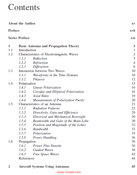
目录
About the Author xv
Preface xvii
Series Preface xxi
1 Basic Antenna and Propagation Theory 1
1.1 Introduction 1
1.2 Characteristics of Electromagnetic Waves 2
1.2.1 Reflection 3
1.2.2 Refraction 4
1.2.3 Diffraction 8
1.3 Interaction between Two Waves 10
1.3.1 Waveforms in the Time Domain 10
1.3.2 Phasors 12
1.4 Polarization 15
1.4.1 Linear Polarization 16
1.4.2 Circular and Elliptical Polarization 16
1.4.3 Axial Ratio 19
1.4.4 Measurement of Polarization Purity 20
1.5 Characteristics of an Antenna 21
1.5.1 Radiation Patterns 22
1.5.2 Directivity, Gain and Efficiency 29
1.5.3 Electrical and Mechanical Boresight 30
1.5.4 Beamwidth and Gain of the Main Lobe 30
1.5.5 Position and Magnitude of the Lobes 32
1.5.6 Bandwidth 33
1.5.7 Polarization 35
1.5.8 Power Handling 36
1.6 Propagation 36
1.6.1 Power Flux Density 36
1.6.2 Guided Waves 38
1.6.3 Free Space Waves 42
References 44
2 Aircraft Systems Using Antennas 45
viii Contents
2.1 Aircraft Systems 45
2.2 Frequencies of the Most Common Aircraft Systems 46
2.3 Automatic Direction Finding 46
2.4 Distress/SOS 49
2.5 Distance Measuring Equipment 49
2.6 Electronic Counter Measures 50
2.7 Electronic Support Systems 51
2.7.1 Frequency 51
2.7.2 Positional Information 51
2.7.3 DOA from Antenna Position 51
2.7.4 DOA Using Amplitude Comparison 52
2.7.5 DOA Using Phase Comparison 54
2.8 Emergency Locator Transmitter/Emergency Position Indicating
Radio Beacon 55
2.9 Global Positioning System 56
2.10 HF 58
2.11 Instrument Landing System 59
2.11.1 ILS Marker 59
2.11.2 ILS Glideslope and Localizer 60
2.12 In-Flight Telephony 63
2.13 Microwave Landing System 64
2.14 Radar 65
2.14.1 Doppler Shift 65
2.14.2 RadAlt 67
2.14.3 Search Radar 67
2.14.4 Weather Radar 68
2.14.5 Synthetic Aperture Radar (SAR) 69
2.14.6 Secondary Surveillance Radar 69
2.15 SatCom Civilian 70
2.15.1 INMARSAT 70
2.15.2 Globalstar 71
2.15.3 Iridium 71
2.15.4 SKYLink 71
2.15.5 Teledesic 71
2.15.6 SatCom Airborne Antennas 71
2.16 Signals Intelligence 73
2.16.1 Communications Intelligence 74
2.16.2 Electronic Intelligence 74
2.17 Tactical Air Navigation 75
2.18 Traffic Collision Avoidance System 76
2.19 Telemetry 77
2.20 UHF 78
2.21 VHF Comms 78
2.22 VHF Omnidirectional Ranging 79
2.23 Equipment Designation 80
References 83
Contents ix
3 The Antenna Siting Process 85
3.1 Introduction 85
3.2 New Antenna Layouts 85
3.3 Optimum Positions for Blades 87
3.4 Design Phase 87
3.4.1 Initial Paper Design Stage 88
3.4.2 Investigative and Computational Modelling Phase 91
3.4.3 Verification and Implementation Phase 95
3.5 Certification and Qualification Phase 97
3.6 Typical Antenna Layouts 97
3.6.1 Small Aircraft 97
3.6.2 Large Aircraft 98
References 101
4 Frequency and Spatial Coverage Considerations 103
4.1 Introduction 103
4.1.1 Standard Ground Planes 103
4.2 Effect of the Structure on the Spatial Characteristics
of the Antenna 104
4.2.1 Uninstalled and Installed Patterns 104
4.3 Combination of Two Waves 105
4.3.1 Combination in the Time Domain 107
4.3.2 Combination of Two Waves Using Trigonometry 111
4.4 Measurements on Scaled Test Bodies 114
4.4.1 Fokker 100 Scaled Model Used for Measurements 114
4.4.2 Cylinder Used for Radiation Pattern Measurements 115
4.5 Effect of Frequency on the Radiation Pattern 117
4.6 Effect of Distance from Obstacles 117
4.6.1 Effect of the Physical Distance from Obstacles 117
4.6.2 Effect of the Electrical Distance from Obstacles 119
4.7 Effect of Wings on the Radiation Pattern 122
4.8 Effect of the Curved Ground Plane and the Electrical Dimensions
of the Fuselage 124
4.8.1 Effect of the Curved Fuselage on the Roll Plane
Patterns 125
4.8.2 Effect of the Curved Nose Cone and Tail on the Pitch
Plane Patterns 128
4.9 Radiation Patterns on Cylinders in the Absence of Obstacles 130
References 131
5 Antennas Used on Aircraft 133
5.1 Introduction 133
5.2 Near and Far Fields of an Antenna 133
5.2.1 Far Field for Wire Antennas 133
5.2.2 Far Field for Aperture Antennas 135
5.3 Antennas on Aerostructures 137
x Contents
5.4 Polar Radiation Patterns 138
5.5 Dipoles 138
5.5.1 Small Dipoles 139
5.5.2 Resonant Dipoles 139
5.5.3 Broadband Dipoles 142
5.5.4 Crossed Dipoles 142
5.5.5 Dipole Arrays 143
5.6 Monopoles 144
5.6.1 Ground Plane Dependence 145
5.6.2 Top Loaded Monopoles 145
5.6.3 Small Monopoles 147
5.6.4 Broadband Monopoles 148
5.6.5 Tuned Monopoles 149
5.6.6 Monopole Arrays 150
5.7 Loops and Notches 150
5.8 Helixes 152
5.9 Flat/Planar Spirals 153
5.10 Patches 156
5.10.1 Patch Arrays 156
5.11 Aperture Antennas 157
5.12 Reflectors 157
5.12.1 Antennas and the Fourier Transform 157
5.13 Waveguide Fed Antennas 170
5.13.1 Waveguide Theory 171
5.13.2 Horns 174
5.13.3 Slotted Waveguide Array Antenna 174
5.13.4 Phased Array Antennas 175
5.14 Model Numbers Used by Different Manufacturers 176
References 178
6 RF Interoperability 179
6.1 Introduction 179
6.2 Coupling between Systems on an Aircraft 179
6.2.1 Conducted Emissions inside the Airframe 180
6.2.2 Radiated Emissions inside the Airframe 181
6.2.3 Radiated Emissions outside the Airframe 181
6.2.4 Conducted Emissions outside the Airframe 181
6.2.5 Radiated Emissions through the Airframe 182
6.2.6 Conducted Emissions through the Airframe 182
6.2.7 Coupling between Systems due to Radiated Emissions Outside the
Airframe 182
6.3 Techniques for Achieving RF Interoperability 183
6.3.1 Antenna Placement 184
6.3.2 Time Domain Measures 184
6.3.3 Sidelobe Blanking 185
6.3.4 Receiver Blanking 185
Contents xi
6.3.5 Frequency Filters 186
6.3.6 EM Shielding 187
6.4 Modulation 190
6.4.1 Amplitude Modulation 191
6.4.2 Single Sideband Modulation 192
6.4.3 Frequency Modulation 192
6.4.4 Pulsed Radar 193
6.5 Coupling due to Radiated Emissions through the Antennas 194
6.6 Coupling between Systems with LOS Antennas 197
6.6.1 Spatial Isolation 198
6.6.2 Calculation of Coupling between Systems with LOS Antennas 200
6.6.3 Out-of-Band Coupling 204
6.7 Coupling between Systems for Antennas on Opposite Surfaces
of the Fuselage 206
6.7.1 Problems with Estimating Coupling at the Higher Frequencies 208
6.8 Existing Formulas Used for Calculating Coupling between Two Antennas
on Opposite Surfaces 210
6.8.1 Bull and Smithers 210
6.8.2 Simple Diffraction 213
6.9 Derivation of an Empirical Formula that Correlates with the
Measured Data 217
References 222
7 Computer Modelling Techniques 223
7.1 Introduction 223
7.2 Overview of Computer Modelling 224
7.2.1 Reasons for Computer Modelling of Antennas on Structures 224
7.2.2 Systems Performance Using Antenna Modelling 225
7.2.3 Postdiction 227
7.2.4 Modelling the Exterior Surface 227
7.2.5 Modelling the Antenna 228
7.2.6 The Frequency Gap 230
7.3 Generic Types of Computer Modelling 230
7.3.1 Classification of Generic Forms of Computer Packages 231
7.3.2 Verification of Modelling by Showing Correlation with Measured
Data 232
7.4 Method of Moments 232
7.4.1 Enhancements 235
7.4.2 Comparison with Scaled Model Measurements 238
7.4.3 Fast Multipole Method – BEM with Accelerated Solver 239
7.5 Finite Difference Time Domain 239
7.5.1 Comparison with Measurements 241
7.6 GTD/UTD 241
7.6.1 Geometric Theory of Diffraction 242
7.6.2 Uniform/Unified Theory of Diffraction 243
7.6.3 Creeping Waves Around Cylinders 243
xii Contents
7.6.4 Limitations of GTD/UTD Modelling 244
7.6.5 Geometric Surface Models for GTD/UTD 247
7.6.6 Higher-Order Interactions 248
7.6.7 Comparison of GTD/UTD with Scaled Model Measurements 249
7.7 Physical Optics 251
7.7.1 Comparison with MoM 252
7.8 Hybrid Methods 252
7.8.1 Multi-domain Method 253
7.8.2 Physical Optics and Hybrid MoM/PO 253
7.8.3 Hybrid of MoM and GTD/UTD 254
7.9 Comparison of Predicted Surface Currents 256
7.9.1 Comparison between the Surface Currents on an Airframe using
Different Codes 257
7.9.2 Surface Currents on a Simplistic Airframe for Different Meshes 259
7.10 Code-to-code Comparison of Radiation Patterns Predicted on the Simplistic
Airframe 261
7.11 Relationship between Number of Unknowns and Surface Area 263
References 265
8 Measurements 267
8.1 Introduction 267
8.2 Positioners 268
8.2.1 Phase Centre Error 269
8.3 Test Facility Antennas 271
8.3.1 Range Antennas 271
8.3.2 Antennas Used in Near-Field Facilities 272
8.3.3 Antennas Used in Compact Ranges 272
8.4 Scaled Models 273
8.4.1 Use of Scaled Models 273
8.4.2 Characteristics of Scaled Models 274
8.5 Scaled Antennas 275
8.5.1 Monopole Antennas 276
8.5.2 Patch Antennas 278
8.6 Absorbers 278
8.6.1 Carbon Loaded Foam RAM 279
8.6.2 Carbon Loaded Fibre Matting 281
8.6.3 Other Types of RAM 281
8.7 Measurement Facilities 281
8.8 Indoor Test Facilities 282
8.9 Anechoic Chambers 282
8.9.1 Quiet Zone 282
8.9.2 Rectangular Chambers 282
8.9.3 Tapered Anechoic Chambers 283
8.10 Compact Ranges 283
8.11 Near-Field Facilities 285
8.11.1 Planar Near-Field Facilities 286
Contents xiii
8.11.2 Cylindrical Near-Field Facilities 287
8.11.3 Spherical Near-Field Facilities 289
8.11.4 Advanced Antenna Near-Field Test System 289
8.12 Outdoor Far-Field Ranges 291
8.12.1 Measurement of the Variation of the Field over the Measurement
Volume 292
8.12.2 Elevated Ranges 292
8.12.3 Slant Ranges 294
8.12.4 Ground Reflection Ranges 294
8.12.5 Open Area Test Sites (OATS) 295
8.13 Ground Test Measurements 297
8.13.1 Radiation Pattern Measurements 298
8.13.2 Coupling Measurements 299
8.14 In-Flight Measurements for System and Inter-System Testing 300
References 301
9 Reference 303
9.1 Centigrade to Fahrenheit Temperature Conversion 303
9.2 Conductivity of Common Metals 303
9.3 Degrees to Radians and Radians to Degrees 304
9.4 Dielectric Constants and Loss Tangents of Common Materials 304
9.5 Electrochemical Series 305
9.6 Electromagnetic Spectrum and Frequency Bands for Different
Nomenclatures 306
9.6.1 EM Spectrum 307
9.6.2 Frequency Bands and Wavelengths for Different Nomenclatures 307
9.7 Formulas 308
9.8 Frequency to Wavelength 318
9.9 Gain in dB and Gain as a Linear Ratio 319
9.10 Greek Alphabet 320
9.11 Imperial to Metric Conversions – Distance, Area, Volume, Speed 320
9.11.1 Conversion Factors for Lengths/Distances 320
9.11.2 Conversion Factors for Areas 320
9.11.3 Conversion Factors for Volume and Capacity 321
9.11.4 Conversion Factors for Speed 321
9.12 Periodic Table Alphabetically 321
9.13 Polarization Matching Matrix 328
9.14 Power in dBm and Power in Watts 328
9.15 Preferred SI Scientific Prefixes 332
9.16 Terms and Definitions 332
9.17 VSWR to Return Loss 337
Appendix: Abbreviations and Acronyms 341
Index 389
专业书籍
下载地址:(回复后可见)
| ![]()