马上注册,结交更多好友,享用更多功能,让你轻松玩转社区。
您需要 登录 才可以下载或查看,没有账号?立即注册

×
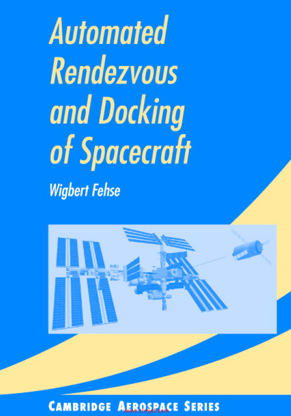
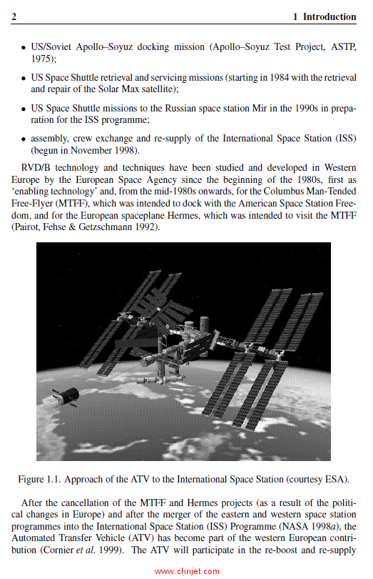
《Automated Rendezvous and Docking of Spacecraft》
航天器自动交会对接
作者:Wigbert Fehse
出版社:Cambridge
出版时间:2003年
《Automated Rendezvous and Docking of Spacecraft》

《Automated Rendezvous and Docking of Spacecraft》

《Automated Rendezvous and Docking of Spacecraft》

《Automated Rendezvous and Docking of Spacecraft》

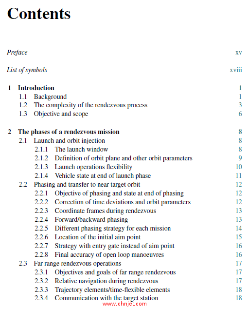
目录
Preface xv
List of symbols xviii
1 Introduction 1
1.1 Background 1
1.2 The complexityof the rendezvous process 3
1.3 Objective and scope 6
2 The phases of a rendezvous mission 8
2.1 Launch and orbit injection 8
2.1.1 The launch window 8
2.1.2 Definition of orbit plane and other orbit parameters 9
2.1.3 Launch operations flexibility 10
2.1.4 Vehicle state at end of launch phase 11
2.2 Phasing and transfer to near target orbit 12
2.2.1 Objective of phasing and state at end of phasing 12
2.2.2 Correction of time deviations and orbit parameters 12
2.2.3 Coordinate frames during rendezvous 13
2.2.4 Forward/backward phasing 13
2.2.5 Different phasing strategyfor each mission 14
2.2.6 Location of the initial aim point 15
2.2.7 Strategywith entrygate instead of aim point 16
2.2.8 Final accuracyof open loop manoeuvres 16
2.3 Far range rendezvous operations 17
2.3.1 Objectives and goals of far range rendezvous 17
2.3.2 Relative navigation during rendezvous 17
2.3.3 Trajectoryelements/time-fle xible elements 18
2.3.4 Communication with the target station 18
x Contents
2.4 Close range rendezvous operations 19
2.4.1 Closing 19
2.4.2 Final approach to contact 21
2.5 Mating: docking or berthing 24
2.5.1 Objectives and end conditions of the mating phase 24
2.5.2 Capture issues 25
2.6 Departure 26
2.6.1 Objectives and end conditions of the departure phase 26
2.6.2 Constraints and issues during departure 26
3 Orbit dynamics and trajectory elements 29
3.1 Reference frames 29
3.1.1 Earth-centred equatorial frame Feq 30
3.1.2 Orbital plane frame Fop 30
3.1.3 Spacecraft local orbital frame Flo 31
3.1.4 Spacecraft attitude frame Fa 32
3.1.5 Spacecraft geometric frames Fge 33
3.2 Orbit dynamics 34
3.2.1 Orbital motion around a centralbody 34
3.2.2 Orbit corrections 37
3.2.3 The equations of motion in the target reference frame 40
3.3 Discussion of trajectoryty pes 41
3.3.1 Free drift motions 42
3.3.2 Impulsive manoeuvres 48
3.3.3 Continuous thrust manoeuvres 58
3.4 Final remark on the equations of motion 72
3.4.1 Examples for combined cases 74
4 Approach safety and collision avoidance 76
4.1 Trajectorysafety– trajectoryde viations 76
4.1.1 Failure tolerance and trajectorydesign requirements 77
4.1.2 Design rules for trajectorysafety 78
4.1.3 Causes of deviations fromthe plannedtrajectory 79
4.2 Trajectorydisturbances 80
4.2.1 Drag due to residual atmosphere 81
4.2.2 Disturbances due to geopotentialanomaly 85
4.2.3 Solar pressure 87
4.2.4 Dynamic interaction of thruster plumes between chaser
and target 89
Contents xi
4.3 Trajectoryde viations generated bythe spacecraft systems 90
4.3.1 Trajectoryde viations due to navigation errors 90
4.3.2 Trajectoryde viations due to thrust errors 93
4.3.3 Trajectoryde viations due to thruster failures 97
4.4 Protection against trajectoryde viations 98
4.4.1 Active trajectoryprotection 98
4.4.2 Passive trajectoryprotection 101
4.5 Collision avoidance manoeuvres 107
5 The drivers for the approach strategy 112
5.1 Overview of constraints on the approach strategy 112
5.2 Launch and phasing constraints 114
5.2.1 The drift of nodes 114
5.2.2 Adjustment of arrival time 115
5.3 Geometrical and equipment constraints 116
5.3.1 Location and direction of target capture interfaces 116
5.3.2 Range of operation of rendezvous sensors 124
5.4 Synchronisation monitoring needs 126
5.4.1 Sun illumination 127
5.4.2 Communication windows 133
5.4.3 Crew activities 136
5.4.4 Time-flexible elements in phasing and approach 137
5.5 Onboard resources and operational reserves 140
5.6 Approach rules defined bythe target 141
5.7 Examples of approach strategies 144
5.7.1 Approach strategy, example 1 144
5.7.2 Approach strategy, example 2 155
5.7.3 Approach strategy, example 3 164
6 The onboard rendezvous control system 171
6.1 Tasks and functions 171
6.2 Guidance, navigation and control 173
6.2.1 The navigation filter 174
6.2.2 The guidance function 180
6.2.3 The control function 184
6.3 Mode sequencing and equipment engagement 203
6.4 Fault identification and recoveryconcepts 207
6.5 Remote interaction with the automatic system 212
6.5.1 Interaction with the GNC functions 213
xii Contents
6.5.2 Manual state update for the automatic GNC system 214
6.5.3 Automatic GNC system with man-in-the-loop 215
7 Sensors for rendezvous navigation 218
7.1 Basic measurement requirements and concepts 219
7.1.1 Measurement requirements 219
7.1.2 Measurement principles 229
7.2 RF-sensors 231
7.2.1 Principles of range and range-rate measurement 231
7.2.2 Principles of direction and relative attitude measurement 238
7.2.3 Measurement environment, disturbances 242
7.2.4 General assessment of RF-sensor application 243
7.2.5 Example: the Russian Kurs system 245
7.3 Absolute and relative satellite navigation 250
7.3.1 Description of the navigation satellite system setup 250
7.3.2 Navigation processing at the user segment 254
7.3.3 Functional principle of differential GPS and relative GPS 260
7.3.4 Measurement environment, disturbances 264
7.3.5 General assessment of satellite navigation for RVD 266
7.4 Optical rendezvous sensors 267
7.4.1 Scanning laser range finder 267
7.4.2 Camera type of rendezvous sensor 272
7.4.3 Measurement environment, disturbances 277
7.4.4 General assessment of optical sensors for rendezvous 279
8 Mating systems 283
8.1 Basic concepts of docking and berthing 283
8.1.1 Docking operations 284
8.1.2 Berthing operations 286
8.1.3 Commonalities and major differences between docking
and berthing 288
8.2 Types of docking and berthing mechanisms 290
8.2.1 Design driving requirements 291
8.2.2 Central vs. peripheral docking mechanisms 293
8.2.3 Androgynous design of docking mechanisms 295
8.2.4 Unpressurised docking/berthing mechanisms 296
8.2.5 Examples of docking and berthing mechanisms 297
8.3 Contact dynamics/capture 305
8.3.1 Momentum exchange at contact 305
Contents xiii
8.3.2 Shock attenuation dynamics 307
8.3.3 Example case for momentum exchange and shock attenuation 312
8.3.4 Devices for shock attenuation and alignment for capture 316
8.3.5 Capture devices 321
8.3.6 The interface between the GNC and the mating system 327
8.4 Elements for final connection 329
8.4.1 Structural latches 330
8.4.2 Seals 333
9 Space and ground system setup 336
9.1 Functions and tasks of space and ground segments 337
9.1.1 General system setup for a rendezvous mission 337
9.1.2 Control responsibilities and controlhierarchy 340
9.2 Ground segment monitoring and control functions for RVD 344
9.2.1 The concept of supervisorycontrol 344
9.2.2 The functions of a support tool for ground operators 346
9.2.3 Monitoring and control functions for the target crew 350
9.3 Communication constraints 353
9.3.1 Data transferreliability 354
9.3.2 Data transmission constraints 356
10 Verification and validation 362
10.1 Limitations of verification and validation 363
10.2 RVD verification/validation during development 364
10.2.1 Features particular to rendezvous and docking 365
10.2.2 Verification stages in the development life-cycle 366
10.3 Verification methods and tools 369
10.3.1 Mission definition and feasibilityphase 370
10.3.2 Design phase 371
10.3.3 Development phase 375
10.3.4 Verification methods for operations and tools for remote
operators 381
10.3.5 Flight item manufacture phase 385
10.4 Modelling of spacecraft items and orbital environment 387
10.4.1 Modelling of environment simulation for RV-control
system test 388
10.4.2 Modelling for contact dynamics simulation 396
10.5 Validation of models, tools and facilities 398
10.5.1 Validation of GNC environment simulation models 398
xiv Contents
10.5.2 Validation of contact dynamics simulation models 402
10.5.3 Validation of simulator programs and stimulation facilities 403
10.6 Major simulators and facilities for RVD 404
10.6.1 Verification facilities based on mathematical modelling 404
10.6.2 Example of a stimulation facilityfor optical sensors 406
10.6.3 Dynamic stimulation facilities for docking 408
10.7 Demonstration of RVD/B technologyin orbit 411
10.7.1 Purpose and limitations of in-orbit demonstrations 411
10.7.2 Demonstration of critical features and equipment 412
10.7.3 Demonstration of RV-system and operations in orbit 417
Appendix A Motion dynamics, by Finn Ankersen 424
A.1 Equations of relative motion for circular orbits 424
A.1.1 General system of differential equations 424
A.1.2 Homogeneous solution 429
A.1.3 Particular solution 431
A.1.4 Discrete time state space system 434
A.1.5 Travelling ellipse formulation 435
A.2 Attitude dynamics and kinematics 437
A.2.1 Direction cosine matrix (DCM) 437
A.2.2 Nonlinear dynamics 438
A.2.3 Nonlinear kinematics 439
A.2.4 Linear kinematics and dynamics attitude model 439
Appendix B Rendezvous strategies of existing vehicles 441
B.1 Space Shuttle Orbiter 441
B.2 Soyuz/Progress 445
Appendix C Rendezvous vehicles of the ISS scenario 450
C.1 International Space Station 451
C.2 Russian Space Station ‘Mir’ 456
C.3 Space Shuttle Orbiter 459
C.4 Soyuz 461
C.5 Progress 463
C.6 ATV 465
C.7 HTV 467
Glossary 470
References 477
Index 486
专业书籍
下载地址:(回复后可见)
| ![]()