马上注册,结交更多好友,享用更多功能,让你轻松玩转社区。
您需要 登录 才可以下载或查看,没有账号?立即注册


x
《Polymer Electrolyte Fuel Cells:Science, Applications, and Challenges》
聚合物电解质燃料电池:科学,应用和挑战
编辑:Alejandro A. Franco
出版社:Taylor & Francis
出版时间:2013年
《Polymer Electrolyte Fuel Cells:Science, Applications, and Challenges》

《Polymer Electrolyte Fuel Cells:Science, Applications, and Challenges》

《Polymer Electrolyte Fuel Cells:Science, Applications, and Challenges》

《Polymer Electrolyte Fuel Cells:Science, Applications, and Challenges》

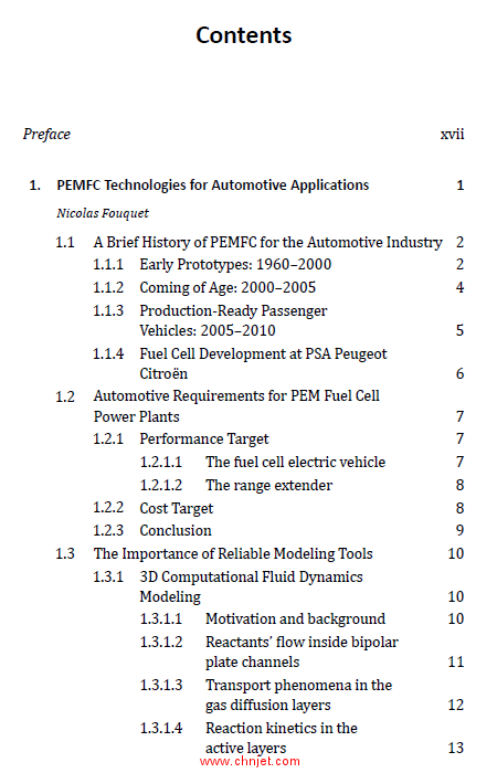
目录
Preface)>> xvii
1. PEMFC Technologies for Automotive Applications 1
)>> Nicolas Fouquet
)>> 1.1)>> A Brief History of PEMFC for the Automotive Industry)>> 2
)>> 1.1.1)>> Early Prototypes: 1960–2000)>> 2
)>> 1.1.2)>> Coming of Age: 2000–2005)>> 4
)>> 1.1.3)>> Production-Ready Passenger
Vehicles: 2005–2010)>> 5
)>> 1.1.4)>> Fuel Cell Development at PSA Peugeot
Citroën)>> 6
)>> 1.2)>> Automotive Requirements for PEM Fuel Cell
Power Plants)>> 7
)>> 1.2.1)>> Performance Target)>> 7
)>> 1.2.1.1)>> The fuel cell electric vehicle)>> 7
)>> 1.2.1.2)>> The range extender)>> 8
)>> 1.2.2)>> Cost Target)>> 8
)>> 1.2.3)>> Conclusion)>> 9
)>> 1.3)>> The Importance of Reliable Modeling Tools)>> 10
)>> 1.3.1)>> 3D Computational Fluid Dynamics
Modeling)>> 10
)>> 1.3.1.1)>> Motivation and background)>> 10
)>> 1.3.1.2)>> Reactants’ flow inside bipolar
plate channels)>> 11
)>> 1.3.1.3)>> Transport phenomena in the
gas diffusion layers)>> 12
)>> 1.3.1.4)>> Reaction kinetics in the
active layers)>> 13
vi Contents
)>> 1.3.1.5)>> Transport phenomena through
the membrane)>> 14
)>> 1.3.1.6)>> Application example:
performance scale-up)>> 14
)>> 1.3.1.7)>> Application example: bipolar
plate design)>> 16
)>> 1.3.1.8)>> Conclusion and further
development)>> 17
)>> 1.3.2)>> Zero-Dimensional Dynamic Modeling)>> 17
)>> 1.3.2.1)>> Motivation and background)>> 17
)>> 1.3.2.2)>> Fuel cell’s impedance model)>> 22
)>> 1.3.2.3)>> Time-resolved EIS
measurements)>> 24
)>> 1.3.2.4)>> Experimental validation)>> 25
)>> 1.3.2.5)>> Limitation and further
development)>> 26
)>> 1.4)>> Conclusion)>> 27
2. Advanced Technologies for Efficient and Low Catalyst
Loading Electrodes 29
)>> Pascal Fugier, Etienne Quesnel, and Sebastien Donet
)>> 2.1)>> Introduction)>> 29
)>> 2.2)>> CVD and Precursors Approach)>> 30
)>> 2.2.1)>> Introduction )>> 30
)>> 2.2.2)>> Precursors Chemistry )>> 33
)>> 2.2.3)>> Precursor Characterization )>> 35
)>> 2.2.3.1)>> Physicochemical characterization
of the precursors )>> 36
)>> 2.3)>> Principles of cvd Process: MOCVD)>> 39
)>> 2.3.1)>> Definition )>> 39
)>> 2.3.2)>> Direct Liquid Injection MOCVD Method )>> 40
)>> 2.3.2.1)>> Introduction)>> 40
)>> 2.3.2.2)>> Typical DLI-MOCVD catalyst)>> 41
)>> 2.3.2.3)>> The precursors)>> 43
Contents vii
)>> 2.3.2.4)>> The carrier gas)>> 44
)>> 2.3.2.5)>> The substrate)>> 45
)>> 2.3.2.6)>> The solvent)>> 45
)>> 2.3.2.7)>> Nucleation and growth)>> 47
)>> 2.3.2.8)>> Precursor oversaturation )>> 47
)>> 2.3.3)>> Fluidized Bed — MOCVD)>> 48
)>> 2.3.3.1)>> Introduction )>> 48
)>> 2.3.3.2)>> Injection system)>> 50
)>> 2.3.4)>> Experimental Results)>> 51
)>> 2.3.4.1)>> Platinum deposition)>> 51
)>> 2.3.4.2)>> Bimetallic electrodes)>> 57
)>> 2.3.4.3)>> Durability tests)>> 59
)>> 2.3.5)>> MOCVD Evolution: Solvent Substitution)>> 65
)>> 2.3.6)>> MOCVD Technico-Economical Survey)>> 66
)>> 2.3.6.1)>> MOCVD industrial prototype)>> 67
)>> 2.3.6.2)>> Details on the
evaporation–injection system)>> 68
)>> 2.3.6.3)>> Details on the FB-system
(deposition chamber + pumping
group + panel control))>> 68
)>> 2.4)>> Physical Vapor Deposition)>> 69
)>> 2.4.1)>> Preliminary Considerations on PVD )>> 70
)>> 2.4.2)>> Conventional PVD for PEMFC:
State of the Art )>> 72
)>> 2.4.2.1)>> Standard sputtering process
for Pt deposition)>> 72
)>> 2.4.2.2)>> Optimized sputtering process
for Pt deposition)>> 76
)>> 2.4.2.3)>> Sputtering process for Pt
alloys)>> 79
)>> 2.4.2.4)>> Conclusion)>> 82
)>> 2.4.3)>> Advanced PVD Techniques )>> 82
)>> 2.4.3.1)>> Catalyst synthesis in a
nanocluster source)>> 83
viii Contents
)>> 2.4.3.2)>> PEMFC electrodes catalyzed
with a nanocluster source)>> 84
3. Electrocatalysis on Shape-Controlled Pt Nanoparticles 93
)>> J. Solla-Gullón, F. J. Vidal-Iglesias, E. Herrero, J. M. Feliu, and A. Aldaz
)>> 3.1)>> Introduction)>> 93
)>> 3.2)>> Synthesis of Shape-Controlled Pt
Nanoparticles)>> 96
)>> 3.3)>> Correlation between Surface Structure
and Nanoparticle Shape)>> 98
)>> 3.4)>> Electrocatalysis on Shape-Controlled
Pt Nanoparticles)>> 103
)>> 3.4.1)>> So-Called Hydrogen
Adsorption–Desorption Process)>> 105
)>> 3.4.2)>> CO Electrooxidation)>> 124
)>> 3.4.3)>> O2 Reduction)>> 128
)>> 3.5)>> Additional Remarks)>> 133
)>> 3.6)>> Conclusions and Outlook)>> 133
4. Ex situ Electrochemical Methods for the Characterization
of PEFC Nanomaterial Degradation 153
)>> Deborah J. Myers and Xiaoping Wang
)>> 4.1)>> Introduction)>> 153
)>> 4.1.1)>> Benefits of ex situ Techniques)>> 153
)>> 4.1.2)>> Aqueous Acidic Electrolyte: Applicability
to the Fuel Cell Environment)>> 154
)>> 4.1.2.1)>> Electrocatalytic activity)>> 154
)>> 4.1.2.2)>> Performance degradation)>> 156
)>> 4.2)>> Electrochemical Techniques)>> 159
)>> 4.2.1)>> Voltammetry)>> 159
)>> 4.2.1.1)>> Catalyst electrochemically active
surface area determination)>> 161
)>> 4.2.1.2)>> Pt and Pt alloy oxide formation)>> 165
)>> 4.2.1.3)>> Carbon support voltammetry)>> 167
)>> 4.2.2)>> Chronoamperometry)>> 171
Contents ix
)>> 4.2.3)>> Electrochemical Impedance
Spectroscopy)>> 172
)>> 4.3)>> Ex situ Techniques/Configurations)>> 174
)>> 4.3.1)>> Non-Hydrodynamic Methods)>> 175
)>> 4.3.2)>> Hydrodynamic Methods )>> 176
)>> 4.3.2.1)>> Rotating ring and ring-disk
electrodes)>> 178
)>> 4.3.2.2)>> Channel flow double
electrode cell)>> 184
)>> 4.3.2.3)>> Requirements for thin-film
electrodes for hydrodynamic
techniques)>> 185
)>> 4.3.3)>> Hybrid Techniques)>> 186
)>> 4.3.3.1)>> Electrochemical quartz
crystal micro and nanobalance)>> 186
)>> 4.3.3.2)>> Differential electrochemical
mass spectrometry)>> 188
)>> 4.3.3.3)>> X-ray spectroscopy
and scattering)>> 190
)>> 4.3.3.4)>> Spectroelectrochemical
Fourier transform
infrared spectroscopy)>> 197
)>> 4.3.3.5)>> Other hybrid techniques)>> 200
)>> 4.4)>> Accelerated Electrochemical Stress Tests for
PEFC Nanomaterial Durability )>> 200
)>> 4.5)>> Examples of Electrochemical Characterization
of PEFC Nanomaterial Degradation)>> 203
5. Microstructural Characterization Methods of PEMFC
Electrode Materials 233
)>> Zhong Xie
)>> 5.1)>> Introduction )>> 233
)>> 5.2)>> Catalyst/Support and Electrode Characterization
for PEMFC)>> 235
)>> 5.2.1)>> 2D Electron Microscopy Techniques)>> 236
)>> 5.2.2)>> 3D Electron Tomography Technique)>> 238
˘ Contents
)>> 5.2.3)>> Porosimetry)>> 242
)>> 5.2.4)>> BET Nitrogen Adsorption–Desorption)>> 244
)>> 5.2.5)>> X-Ray Photoelectron Spectroscopy )>> 246
)>> 5.3)>> Structural Characterization of Polymer
Electrolyte Materials)>> 249
)>> 5.3.1)>> SAXS/SANS)>> 250
)>> 5.3.2)>> AFM)>> 252
)>> 5.3.3)>> 3D Tomography )>> 255
)>> 5.3.3.1)>> TEM tomography)>> 256
)>> 5.3.3.2)>> Focused ion beam
tomography)>> 256
)>> 5.3.3.3)>> X-ray tomography)>> 258
)>> 5.3.4)>> Fourier Transform Infrared
Spectroscopy )>> 259
)>> 5.3.5)>> Nuclear Magnetic Resonance
Spectroscopy)>> 261
)>> 5.3.6)>> X-Ray Photoelectron Spectroscopy )>> 264
)>> 5.3.7)>> X-Ray Diffraction)>> 265
)>> 5.4)>> Prospective and Outlook )>> 266
6. Instability of Nanomaterials in PEFC Environments:
A State of the Art 277
Sarah Ball
)>> 6.1)>> Introduction)>> 278
)>> 6.2)>> Decay Mechanisms at PEFC Cathode)>> 279
)>> 6.2.1)>> Factors Influencing Surface Area Loss and
Performance Decay in High-Surface-Area
Pt/C Catalysts )>> 282
)>> 6.2.1.1)>> Pt dissolution/re-precipitation
Ostwald ripening and Pt
re-precipitation in the
electrolyte phase)>> 282
)>> 6.2.1.2)>> Pt detachment from the carbon
support)>> 286
)>> 6.2.1.3)>> Agglomeration of Pt particles)>> 288
Contents xi
)>> 6.2.1.4)>> Effect of voltage cycle regime)>> 289
)>> 6.2.2)>> Benefits of Pt Alloys Over High-Surface-Area
Pt-Only Catalysts at the PEMFC Cathode)>> 295
)>> 6.2.2.1)>> Activity and cost benefit of Pt
alloys vs. Pt only )>> 295
)>> 6.2.2.2)>> Binary and ternary alloys —
influence of alloying element
on stability)>> 300
)>> 6.2.2.3)>> Binary alloys — effects of
de-alloying and acid leaching)>> 301
)>> 6.2.2.4)>> Ternary alloys at the PEMFC
cathode — stability and
performance benefits)>> 311
)>> 6.2.2.5)>> Alternative precious metal
(non-Pt) alloys for the
ORR — activity and stability)>> 312
)>> 6.2.3)>> Core–Shell Catalysts and Novel Structures
for the PEMFC Cathode)>> 313
)>> 6.2.4)>> Non-Precious Metal ORR Catalysts)>> 318
)>> 6.3)>> Decay Mechanisms at the PEMFC
Anode — Hydrogen and Reformate)>> 320
)>> 6.3.1 Factors Influencing Surface Area Loss
and Performance of High-Surface-Area
Pt/C Anodes)>> 322
)>> 6.3.2)>> Benefits of Pt Alloys Over High-Surface-Area
Pt-Only Catalysts at the PEMFC
Anode — Tolerance to Impurities, Cost
Reduction, and Durability)>> 325
)>> 6.3.3)>> Durability Implications of Alternative
Strategies to Achieve CO Tolerance — Air/
Oxidant Bleeding, Increased Temperature,
and Bilayer Structures )>> 329
)>> 6.3.4)>> Use of Non-Platinum and Non-Precious
Metal Catalysts at the PEMFC Anode
for HOR)>> 330
)>> 6.4)>> Conclusions and Outlook)>> 330
xii Contents
7. Innovative Support Materials for Low-Temperature
Fuel Cell Catalysts 341
)>> Ernesto Rafael Gonzalez and Ermete Antolini
)>> 7.1)>> Introduction)>> 341
)>> 7.2)>> Carbon)>> 344
)>> 7.2.1)>> Ordered Mesoporous Carbons )>> 347
)>> 7.2.2)>> Carbon Nanotubes (CNTs))>> 350
)>> 7.3)>> Ceramic)>> 355
)>> 7.3.1)>> Inorganic Metal Oxides)>> 355
)>> 7.3.1.1)>> Ti-based oxides )>> 355
)>> 7.3.1.2)>> Sn-based oxides)>> 360
)>> 7.3.1.3)>> WOx )>> 364
)>> 7.3.1.4)>> RuO2·â†œxH2O)>> 368
)>> 7.3.2)>> Tungsten Carbides)>> 369
)>> 7.4)>> Polymer)>> 375
)>> 7.4.1)>> PAni)>> 375
)>> 7.4.2)>> PPy)>> 380
)>> 7.4.3)>> PTh)>> 384
)>> 7.5)>> Conclusions)>> 389
)>> 7.5.1)>> Carbon Materials)>> 389
)>> 7.5.2)>> Ceramic Materials )>> 390
)>> 7.5.3)>> Polymer Materials)>> 390
8. Membrane Degradation Mechanisms in a Polymer
Electrolyte Fuel Cell 401
)>> Panagiotis Trogadas and Thomas F. Fuller
)>> 8.1)>> Introduction)>> 401
)>> 8.2)>> Mechanical Degradation)>> 402
)>> 8.3)>> Thermal Degradation)>> 403
)>> 8.4)>> Chemical Degradation of PEM)>> 409
)>> 8.5)>> Role of Metal Impurities in Chemical
Degradation)>> 414
)>> 8.6)>> Evidence of Preferential Degradation)>> 414
)>> 8.7)>> Experimental Measurement of Chemical
Degradation)>> 415
)>> 8.8)>> Concluding Remarks)>> 415
Contents xiii
9. Effects of Fuel and Air Impurities on PEFC Performance 427
)>> Eben Dy, Zheng Shi, Khalid Fatih, Jiujun Zhang,
and Zhong-Sheng Liu
)>> 9.1)>> Introduction)>> 428
)>> 9.2)>> Fuel Side Impurities)>> 429
)>> 9.2.1)>> Sources of Fuel Impurities)>> 429
)>> 9.2.2)>> Carbon Oxides Poisoning)>> 430
)>> 9.2.2.1)>> Carbon monoxide impacts)>> 430
)>> 9.2.2.2)>> Carbon monoxide contamination
mechanism)>> 434
)>> 9.2.2.3)>> Carbon dioxide contamination)>> 436
)>> 9.2.3)>> Hydrogen Sulfide Poisoning)>> 437
)>> 9.2.3.1)>> Hydrogen sulfide impacts)>> 437
)>> 9.2.3.2)>> Hydrogen sulfide contamination
mechanism)>> 439
)>> 9.2.4)>> Ammonia)>> 441
)>> 9.2.4.1)>> NH3 impacts)>> 441
)>> 9.2.4.2)>> NH3 poisoning mechanism)>> 442
)>> 9.2.7)>> Multi-Contaminants Impacts)>> 444
)>> 9.3)>> Air Side Impurities)>> 446
)>> 9.3.1)>> Sources of Impurities)>> 446
)>> 9.3.2)>> Sulfur Oxides )>> 447
)>> 9.3.2.1)>> SOX impacts)>> 447
)>> 9.3.2.2)>> SOX contamination mechanism)>> 449
)>> 9.3.3)>> Nitrogen Oxides (NOX↜))>> 451
)>> 9.3.3.1)>> NOX impacts)>> 451
)>> 9.3.3.2)>> NOX contamination mechanism)>> 452
)>> 9.3.4)>> Hydrogen Sulfide and Ammonia)>> 454
)>> 9.3.4.1)>> H2S and NH3 impacts)>> 454
)>> 9.3.4.2)>> H2S and NH3 contamination
mechanism)>> 455
)>> 9.3.5)>> Volatile Organic Compounds and
Salt (NaCl))>> 456
)>> 9.3.5.1)>> Volatile organic compounds )>> 456
)>> 9.3.5.2)>> NaCl/Na+ and Cl– ions)>> 458
xiv Contents
)>> 9.4)>> Mitigation Strategy)>> 460
)>> 9.4.1)>> Fuel-Side Mitigation)>> 460
)>> 9.4.1.1)>> Pre-treatment of reformate)>> 460
)>> 9.4.1.2)>> Air/Oxygen bleeding)>> 461
)>> 9.4.1.3)>> CO-tolerant catalyst)>> 462
)>> 9.4.1.4)>> High-temperature operation)>> 464
)>> 9.4.1.5)>> Hydrogen from electrolysis
of water)>> 466
)>> 9.4.2)>> Air Side Mitigation )>> 466
)>> 9.4.2.1)>> Filtration )>> 466
)>> 9.4.2.2)>> Potential cycling and flushing )>> 468
)>> 9.5)>> Summary)>> 469
10. In situ Characterization Methods of PEMFC Materials
Degradation 487
)>> Viktor Hacker, Eva Wallnöfer-Ogris, Harald Brandstätter,
and Markus Perchthaler
)>> 10.1)>> Introduction)>> 487
)>> 10.2)>> Hydrogen Diffusion: In situ Determination of
Membrane Degradation)>> 488
)>> 10.3)>> Polarization Curves and Performance)>> 489
)>> 10.4)>> Open-Circuit Voltage)>> 490
)>> 10.5)>> Fluoride Emission Rate)>> 491
)>> 10.6)>> Cyclic Voltammetry)>> 493
)>> 10.7)>> Electrochemical Impedance Spectroscopy)>> 496
)>> 10.7.1)>> Equivalent Circuit Models)>> 496
)>> 10.7.2)>> Total Harmonic Distortion Analysis)>> 497
)>> 10.8)>> Determination of the Local Electrochemical
Potential)>> 498
)>> 10.9)>> Exhaust Gas Analysis)>> 500
)>> 10.10)>> Current Density Distribution)>> 503
)>> 10.10.1)>> Humidification Aspects:
Co-Flow Operation)>> 504
)>> 10.10.2)>> Humidification Aspects:
Counter-Flow Operation)>> 505
Contents xv
11. Multiscale Molecular Modeling of Degradation
Phenomena in Catalyst Layers of Polymer
Electrolyte Fuel Cells 511
Kourosh Malek and Tetsuya Mashio
11.1 Introduction 512
11.2 Multiscale Molecular Modeling of CL 514
11.2.1 Molecular Dynamics Simulations 515
11.2.2 Atomistic MD Simulations of CL 517
11.2.3 Meso-Scale Model of CL Microstructure 519
11.3 Pt Degradation and Molecular Modeling of
Pt Stability and Pt–C Interactions 521
11.3.1 Pt Nanoparticle Migration and
Formation of Larger Clusters 522
11.3.2 Pt Dissolution 530
11.4 Meso-Scale Modeling of Carbon Corrosion
in CLs 533
11.5 Concluding Remarks 538
12. Toward a Bottom-Up Multiscale Modeling Framework
for the Transient Analysis of PEM Fuel Cells Operation 549
Alejandro A. Franco
12.1 Introduction 549
12.2 Modeling of the Electrochemistry in PEMFCs 554
12.3 Modeling of Transport and Thermal Stresses
in PEMFCs 561
12.4 Bottom-Up Multiscale Modeling of PEMFC 566
12.5 CFD Modeling of PEMFC 572
12.6 PEMFC Diagnostic Modeling 574
12.7 Summary and Challenges 576
Index 589
专业书籍
下载地址:(回复后可见)
| ![]()
![]()